References
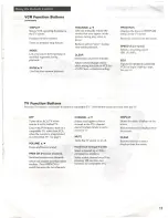
Location
of
Controls
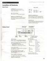
Back Panel
Back of
VCR
IN
FROM
ANT
(Antenna) Connector
Receives a signal from an
antenna
or cable
QD
oa noo
system
when
attached.
AUDIO
py
4
OUT TO
TV
Connector
Passes signal to
TV
using
the cable
supplied.
VIDEO
IN
and
AUDIO
IN
Jacks
VIDEO
OUT
and
AUDIO OUT Jacks
Receives signals from
another
component
like
a
Sends sienals from
VCR
to
antisisonin
VCR
or camcorder
when
it
is
connected to these
like
a V
y=
6
camooriei
ait
d
jacks. Use the
INPUT
button
on the
VCR
to select.
to these jacks.
CH3 CH4 Switch
Selects the channel to which you will
tune
the
TV
to see the
VCR
picture
if you connect the
VCR
using
one of the basic hookups.
2
Current
Time
or
Channel Number or
Display Panel
Time
Counter
Line
Indicator
(L)
FIT
TIMER
I
i
ver11
DD
!
!
TIMER
VCR
Situs
|
Cassette-In Indicator
Indicator
Indicator
Indicators
—
—
f=
Tape Speed Indicators
Status Indicators
Show
what
the VCR
is
doing.
Indicator
Lights
when
VCR is
set for timer
recording and
VCR is
turned
off. Flashes
if
tape
is
not inserted.
» and
Record
18
and
Record-pause
VCR
Indicator (Applies Only
to Basic
Hookups)
Press
TV/VCR
to
turn
on or
off.
»
Playback
VCR
indicator on: Picture from
VCR.
"
Play-pause
VCR
indicator
off:
Picture from
TV
channel.
18
and
flashing »
Frame advance
Slow motion
Time or
Time Counter
’
Press
DISPLAY
to switch between the
current
time
A
Rewind
and
elapsed-time counter.
<< flashing
Reverse search
:
>»
Fast
forward
Tape Speed Indicators
(SP,
LP,
or
SLP)
we
lashing
em
Press
TAPE
SPEED on
VCR
or SPEED on the
remote to change,
Cassette-in Indicator
(53)
Channel Number or
Line
Input
(L)
Lights when
a
tape
is
in the
VCR.
The channel
number
or
line
input
is
displayed.
Press
INPUT
on
VCR
to light
L
to record from the
VIDEO
IN
and
AUDIO
IN
jacks.
25
Summary of Contents for VR526A
Page 1: ......

