Series 1780 Dynamometer User Manual V1.1
Document ID: Q2D4F5
Publish date: 2020-03-06
4.1.4 Final assembly of the support
❏
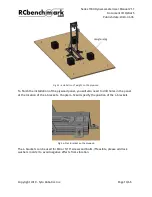
[You will need TWO persons to finish the following work] To connect the upper and
lower part, place the upper support that you built previously and place at the middle
of lower assembly, as shown below:
Fig 4.13: Gather your two previous assemblies
❏
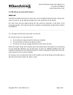
Insert one button head 5/16-18” screw (#KEDB) into the free side of the aluminum rod
(#DUSQ) and one end-feed T-nut 5/16-18” (#YREC), and then connect it to the T-slotted
3’ double beam (#LNKY). Repeat for the other side.
❏
ATTENTION: the angle (alpha on Fig. above) between the aluminum side rod and the
ground shall be between 50 to 60 degrees in order to minimize the buckling effect and
the load on the structure.
❏
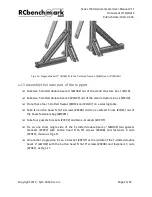
Take all of L-brackets (#KPHT) out of the accessories and fasteners for assembly box
(#BCJE).
❏
Take eight button head 5/16-18” screws (#KEDB) and eight end-feed T-nut 5/16-18”
(#YREC).
❏
Insert one button head screw (#KEDB) into one L-bracket and connect the other side
with one end-feed T-nut 5/16-18”. Leave the other side of the L bracket free. Repeat
this step for all L-brackets.
Copyright 2019 - Tyto Robotics Inc.
Page 25/65


