-
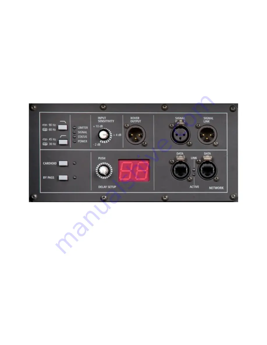
Cardioid set-up switch
-
By-pass switch
-
RDNet input output Ethercon connectors
-
4 status LEDs
The TTS26-A amplifier section features:
-
3400 Watt Digital amplifier modules with
-
PFC circuit
-
System cooling speed controlled fans
-
Powercon AC input- output connectors
-
Vibrostop floating aluminum panel
REAR PANEL FEATURES AND CONTROLS
1 MAIN SIGNAL XLR INPUT (BAL/UNBAL)
. The system accept female XLR input connectors and line-
level signals from a mixing console or other signal source.
2 SIGNAL LINK XLR OUTPUT
. The output XLR male connector provides a loop trough for speakers
daisy chaining.
3 XOVER SIGNAL OUTPUT
.
The output XLR male connector provides a crossover high passed signal
(24 dB/octave) for satellites speakers.
4
INPUT SENSITIVITY
.
Controls the overall signal level at the input to the power amplifier. The
control ranges from + 10 dBu (maximum attenuation) to the –2 dBu sensitivity (maximum input
gain). The centre detent is +4 dBu (nominal level required to drive the amplifier at maximum
power).
5
XLOW CUT 30/45 Hz.
This switch provides an high pass 24 dB/octave filtering at 30 or 45 Hz.
This is really useful for indoor situations (no very low frequencies that can create resonant sound)
or when all the power shall be used in the 45 Hz – 150 Hz range.
6
XOVER 90/150 HZ.
Provides 24 dB/octave low-pass filtering at 90 Hz if released, at 150 Hz if
pressed. The same crossover frequency in high-pass is available from XOVER OUTPUT XLR.
7
TIME DELAY ENCODER.
This encoder provides a time delay setting expressed in meters.
8
TIME DELAY DISPLAY.
Display the time delay setting.
9
POWER INDICATOR.
Power on indicator. When the power cord is connected and the power switch
is turned on this indicator lights green.


