background image

10

STATUS INDICATOR.  

The status indicator blink orange if the main amplifier or power supply is in 

faulty condition. If the status indicator lights orange, switch o

ff

 the amplifier and call the closest 

RCF SERVICE CENTRE.

11

SIGNAL INDICATOR.  

The signal indicator lights green if there is signal present on the main XLR 

input.

12 LIMITER INDICATOR.  

The amplifier has a built in compressor/limiter circuit to prevent clipping of 

the amplifiers or overdriving the transducers.

When the compressor is active the led is blinking yellow. When the soft clipping circuit is active 

the LED blinks orange. It is okay if the limit LED blinks occasionally. If the LED blinks frequently or 
lights continuously, turn down the signal level.


The amplifier has a built in RMS limiter. If the RMS 

limiter is active the LED lights red. The RMS limiter has the purpose to prevent damages the 
transducers. The speaker shall never be used with the limit indicator red, continuously. Continuous 
operation with the RMS protection active can cause damages to the speaker. 

13 CARDIOID SET-UP SWITCH. 

This switch provides a special equalisation and delay setting to create 

a cardioid pattern when the system is used in conjunction with two other TTS56-A modules.

14 BY PASS SWITCH. 

Pressing this switch it is possible to by-pass the RDNet user setting preloaded 

on the module.

15 DATA INPUT ETHERCON CONNECTOR. 

RDNet


Input CAT5 Ethercon connector. 

16 DATA LINK ETHERCON CONNECTOR.

 RDNet


Link CAT5 Ethercon connector.

17 LINK LED.

 This green led is on if the module is addressed from the RDNet controller

18

ACTIVE LED. 

This green led is blinking if the RDNet communication is active.

19

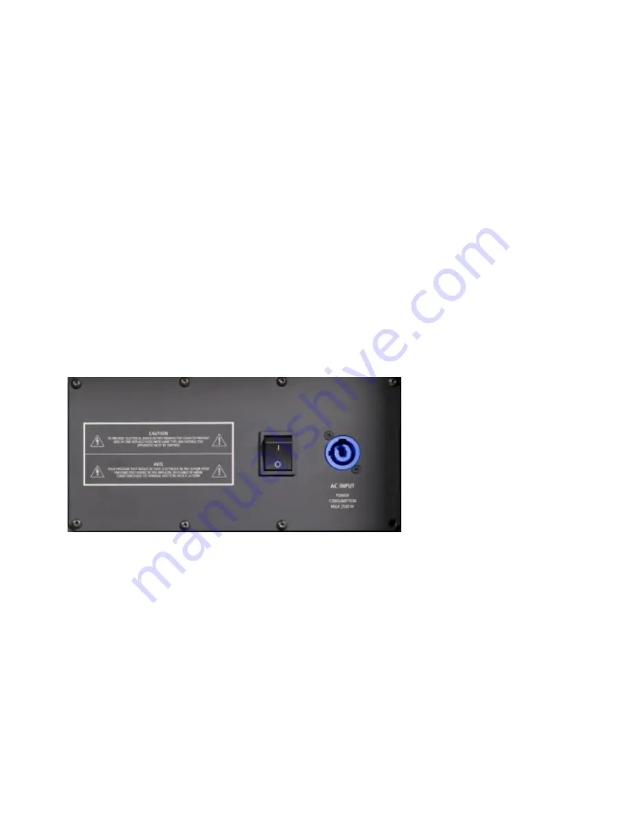
POWER MAIN SWITCH

. The power switch turns the AC power ON and OFF. Make sure that the 

sensitivity is set to + 10 dBu when you turn on the speaker.

20

AC POWERCON RECEPTACLE.


RCF TT+ series uses a POWERCON locking 3-pole AC mains. Always 

use the specific power cord provided in the package.

CONNECTIONS

The XLR connectors use the following AES standard:

PIN 1

=

GROUND (SHIELD)

PIN 2

=

HOT (+)

PIN 3

=

COLD (-)

BEFORE TURNING ON THE SPEAKER

At this point you can connect the power supply cable and the signal cable, but before turning on the 
speaker make sure that the volume control is at the minimum level (even on the mixer output). It is 
important that the mixer is already ON before turning on the speaker. This will avoid damage to the 
speakers and noisy “bumps” due to turning on parts on the audio chain. It is a good practice to always 
turn on speakers at last and turn them o

ff

 immediately after the show.

Now you can turn ON the speaker and adjust the volume control to a proper level.

TIME DELAY SETTING

Summary of Contents for TTS26-A

Page 1: ...d the design of our TT speakers with a clear idea in mind maximum high quality audio SPL in the smallest weight and size Thanks to our state of the art neodymium transducers premium quality analog pro...

Page 2: ...off and disconnect the power cable 10 If the amplifier begins to emit any strange odours or smoke switch it off immediately and disconnect the power supply cable 11 Do not connect this product to any...

Page 3: ...ower transformers mains cables lines that supply loudspeakers OPERATING PRECAUTIONS Do not obstruct the ventilation grilles of the unit Situate this product far from any heat sources and always ensure...

Page 4: ...N RCF is one of only a few loudspeaker manufacturers worldwide who have the ability to completely design and manufactures transducers speaker systems and amplification and control electronics Our 50 p...

Page 5: ...overall signal level at the input to the power amplifier The control ranges from 10 dBu maximum attenuation to the 2 dBu sensitivity maximum input gain The centre detent is 4 dBu nominal level require...

Page 6: ...A modules 14 BY PASS SWITCH Pressing this switch it is possible to by pass the RDNet user setting preloaded on the module 15 DATA INPUT ETHERCON CONNECTOR RDNet Input CAT5 Ethercon connector 16 DATA...

Page 7: ...again to confirm the setting CARDIOID SET UP It is possible to create subwoofer cardioid systems using groups of three modules A group is made of three modules the group shall be made as follow 2 modu...

Page 8: ...input board and reads the RDNet user settings last configuration saved BY PASS SWITCH released LED OFF The system reads the input board and bypass the user setting eventually loaded ion the speaker l...

Page 9: ...oofer features top pole mount cap for professional 35 mm speaker pole mount top plates to assembly a TTL11 A system on top of a TTS26 A subwoofer WARNING Never suspend TT speakers by there handles Han...

Page 10: ...L 419 Series 13360145 AC POWER BOX 6XTTL55 EUROPEAN STAGE BOX TO POWER 6 TTL55 A LINE ARRAY MODULES OR 6 TTS56 A MODULES 1 piece for 6 pieces OF TTS26 SUB are suggested Full compatibility with Socapex...

Page 11: ...a subito gravi danni oggetti o liquidi sono entrati nell apparecchio l apparecchio ha subito forti urti 5 Qualora questo prodotto non sia utilizzato per lunghi periodi togliere la tensione dal cavo di...

Page 12: ...icinanze di apparecchiature che producono campi elettromagnetici di forte intensit per esempio trasformatori di grande di potenza cavi di rete linee che alimentano altoparlanti PRECAUZIONI D USO Non o...

Page 13: ...ra esperienza di oltre 50 anni nel settore audio abbinata ai nostri avanzati processi di ricerca e sviluppo nonch di produzione ci permette di integrare perfettamente tutti gli ingredienti che compong...

Page 14: ...R maschio fornisce un uscita audio passa alto 24 dB ottava per diffusori satellite 4 SENSIBILITA IN INGRESSO Controlla il livello del segnale in ingresso all amplificatore di potenza Il controllo vari...

Page 15: ...di 3 subwoofers 14 PULSANTE BY PASS Premendo questo pulsante possibile by passare le impostazioni utente pre caricate sul modulo 15 CONNETTORE DATA INPUT ETHERCON Connettore RDNet Input CAT5 Ethercon...

Page 16: ...l diffusore e alzare il controllo di livello a seconda delle necessit IMPOSTAZIONE DEL RITARDO TEMPORALE TIME DELAY Il ritardo espresso in metri Le risoluzione del ritardo di 0 1 fino a 10 metri ed 1...

Page 17: ...ione RDNet Utilizzando un controller RDNet possibile ricevere informazioni di stato del sistema stato degli amplificatori dei segnali delle impostazioni inviare comandi al sistema mute solo variazioni...

Page 18: ...ante by pass premuto la seguente Sensitivity Sensibilit 4 dBu High pass Passa alto 30 Hz Low pass Passa basso 150 Hz Cardioid Cardioide OFF Delay Ritardo 0 Bypass By pass OFF User filters Filtri utent...

Page 19: ...ssionale in acciaio da 35 mm Piastre per l installazione di un sistema TTL11 A sopra ad un sub TTS26 A ATTENZIONE Non sospendere mai il diffusore per mezzo delle maniglie Le maniglie sono state proget...

Page 20: ...ibilit con Socapex Serie SL 419 13360145 AC POWER BOX 6XTTL55 STAGE BOX EUROPEO PER ALIMENTARE 6 TTL55 A O 6 TTS56 A 1pezzo ogni 6 moduli di TTS26 A Completa compatibilit con Socapex Serie SL 419 1336...

Page 21: ...t XLR male female Power Input Output Powercon male female RDNet Input Output Cat5 Ethercon CONTROLS DSP Controls Sensitivity Control 2 dBu 10 dBu X low cut X over selection Delay set up Cardioid setti...

Reviews: