background image

7

ENGLISH

Each speaker has 2 audio inputs, of which one has priority.

VSA

 II

 speakers can be installed very close to the wall (to be unobtrusive) thanks to their 

compact sizes, slim shapes and their (included) wall mounting accessories.

SWM-BR 

VSA 

II

 optional accessory: each kit includes a pair of swivel brackets for a single 

VSA 

II 

speaker wall mounting, allowing a horizontal angle pointing up to 60°.

Connections are separated: AC and DC power supply at one end, audio signals and interfaces 
on the other. The electrical connections are clearly labelled and made through screw terminals 
and other suitable and easy-to-wire connectors.

VSA 

II 

series (standard version) is intended for indoor sound systems only.

INSTALLATION

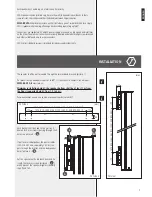
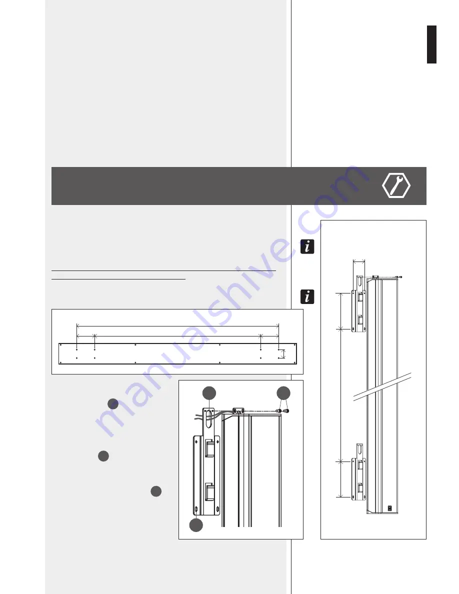
The speaker shall be wall-mounted through the two included brackets (picture 1).

T

o


swivel


iT


wiTh


a


horizonTal


angle


up


To

 60°, 

iT


is


necessary


To


purchase


The


opTional


SWM-BR VSA II


accessory


kiT

.

Minimum installation height: the speaker bottom shall be at least 1 m from 
the floor (suggested height: from 1.5 to 3 m).

T

he


wood


package


lid


can


also


be


used


as


drilling


TemplaTe

 (

picTure

 2)! 

Each bracket shall be fixed to the wall by  4 
dowels for 5 mm screws (passing through the 4 
holes, see picture 3 – 

A

). 

If put to recessed pipelines, the power cables 
(230-115 V ac and, separately, 24 V dc) can 
pass through the bracket and the loudspeaker 
holes (picture 3 – 

B

).

Put the speaker on the bracket hooks and fix 
it with the security screws (picture 3 – 

C

), 

which prevent the speaker might accidentally 
slip off and fall. 

A

B

C

PICTURE 3

PICTURE 1

PICTURE 2

1910 (VSA 2050

 II

), 1202 (VSA 1250

 II

), 848 (VSA 850

 II

)

170

170

80

80

170

170

1570 (VSA 2050),

 862 (VSA 1250),

 508 (VSA 850)

1570 (VSA 2050

 II

), 862 (VSA 1250

 II

), 508 (VSA 850

 II

)

[mm]

[mm]

Summary of Contents for VSA 1250 II

Page 1: ...USER MANUAL MANUALE D USO VSA 2050 II VSA 1250 II VSA 850 II DIGITALLY STEERABLE ARRAY SPEAKER SYSTEMS DIFFUSORI ATTIVI DIGITALI DI TIPO ARRAY ...

Page 2: ... socket outlet with a protective earthing connection Protect the power cord from damage Make sure it is positioned in a way that it cannot be stepped on or crushed by objects To prevent the risk of electric shock never open this product there are no parts inside that the user needs to access 2 2 24 V dc SECONDARY POWER SUPPLY BY BATTERIES The apparatus operating voltage is 24 V dc therefore it is ...

Page 3: ...that are recommended by the manufacturer The equipment support trolley assembly must be moved with extreme caution Sudden stops excessive pushing force and uneven floors may cause the assembly to overturn 10 Mechanical and electrical factors need to be considered when installing a professional audio system in addition to those which are strictly acoustic such as sound pressure angles of coverage f...

Page 4: ...ence The signal is fully processed and amplified in the digital domain thanks also to 6 FPGAs Field Programmable GateArray that manage all the data inside the speaker system The circuitry is modular to get maximum reliability and easy servicing VSA II speakers include 2 independent power supply units controlled by a microprocessor for either AC 230 115 V or DC 24 V operation to get full back up fa...

Page 5: ...ugh the two included brackets picture 1 To swivel iT wiTh a horizonTal angle up To 60 iT is necessary To purchase The opTional SWM BR VSA II accessory kiT Minimum installation height the speaker bottom shall be at least 1 m from the floor suggested height from 1 5 to 3 m The wood package lid can also be used as drilling template picture 2 Each bracket shall be fixed to the wall by 4 dowels for 5 m...

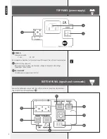
Page 6: ...r cord Before powering up make sure the mains voltage corresponds to the voltage indicated on the unit label 3 24 Vdc INPUT Secondary power supply input 24 V dc TOP PANEL power supply BOTTOM PANEL signals and commands 4 7 6 9 10 5 8 1 2 3 Remove the bottom panel cover with the 4 LEDs to access to connections by disconnec ting its cable from the respective port 10 ...

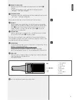
Page 7: ... input activated when the and GND pins are short circuited It has no effect if the PRIORITY 6 command is present The speaker has also an automatic stand by mode after ca 30 minutes without detecting any audio signal When in automatic stand by mode the speaker will automatically turn on as soon as an audio signal is detected on the selected input 8 MONITORING Dry contacts normally closed common nor...

Page 8: ...ght laws and is to be used to configure the RCF RDNET system devices only It is not allowed to modify or change or try to decompile this software In no event shall RCF S p A be liable to end users for any damage whatsoever including but not limited to financial damages for loss of business profits or business information due to the software use or inability to use this product The foregoing provis...

Page 9: ...ssible to change the installation folder directory of the RDNET software or keep the default path Click INSTALL to proceed As soon as the installation ends it will be necessary to reboot your computer Choose either Reboot Now to reboot immediately or I want to reboot later to reboot later manually Click FINISH to quit ...

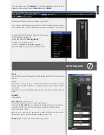
Page 10: ...rams RCF RDNet RDNet or double click RDNet icon on the desktop First in the main menu click Go and then Controllers In the Controllers section bottom left in the main window click Match All or click each single Match button or simply drag and drop to add all linked USB devices COM to the Workspace Controllers list bottom right in the main window CONFIGURATION BY RDNET SOFTWARE ...

Page 11: ...e VSA speaker all MUTE buttons get red Click MUTE again to unmute SOLO This function is useful only when an RdNet network with several speakers is present through either a RDNET CONTROL 8 or CONTROL 2 device Read the RdNet software user manual Click SOLO to make the selected VSA speaker the only one activated while the others are muted STANDBY Stand by mode M1 to M20 buttons on the left VSA test m...

Page 12: ...detecting any audio signal and turn on as soon as an audio signal is detected on the selected input or due to the activation of the priority function Set AUTO STAND BY to OFF to disable this function ACTIVE EQUALIZER The equalization can be chosen among 6 different settings 3 are presets and 3 are editable by the user custom 1 2 3 FLAT no equalization flat frequency response SPEECH equalization op...

Page 13: ...CUS mode from 2 to 6 metres 0 1 m steps in the FREE BEAM mode 3a EASY BEAM Set the listening area D through AUDIO RANGE Both minimum D1 and maximum D2 distances from speaker can be selected among several presets according to the speaker height H 3b EASY FOCUS Set the maximum distance to be covered through FOCUS 3c FREE BEAM Set the TILT and then the BEAM 1 First select the SETTINGS MODE EASY BEAM ...

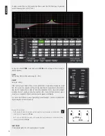
Page 14: ...e EQ graph Type DISABLED the filter is disabled by pass PEQ parametric equalizer that allows to adjust the level at the settable centre frequency and specify the Q factor the adjusted level can be widened or narrowed SHELVING HIGH increase or decrease the level of all frequencies above the selected frequency by the specified amount SHELVINGLOW increaseordecreasethelevelofallfrequenciesbelowthesele...

Page 15: ... it sends without storing the equalization to the VSA speaker For each filter frequency and gain can be adjusted either graphically through the mouse by dragging the little coloured square or in an analytical way by inserting values in cells or rotating controls The overall equalization is shown as a red line the intervention of the selected filter as a green line the intervention of a filter that...

Page 16: ...s setting a delay time directly proportional to the distance from the first speaker line in order to reduce the perception of echo due to the different reception times of sounds coming from speakers that are distant one another give a correct sense of depth to listeners and improve the speech intelligibility You can set the distance in meters graphically or analytically or the time in milliseconds...

Page 17: ...bit floating point DSP Spartan3A FPGA 24 bit AD converters 48 kHz Operation 20 PEQ channels compression beam forming 20 limiters and protections AMPLIFIERS Type 20 class D amplifiers 12 class D amplifiers 8 class D amplifiers Power each amplifier 50 W 50 W 50 W POWER SUPPLY AC power supply either 230 V or 115 V according to the model 50 60 Hz type switching Consumption stand by 26 W 21 W 18 W oper...

Page 18: ...Emilia Italy Tel 39 0522 274 411 Fax 39 0522 232 428 e mail info rcf it Salvo eventuali errori ed omissioni RCF S p A si riserva il diritto di apportare modifiche senza preavviso Except possible errors and omissions RCF S p A reserves the right to make modifications without prior notice ...

Reviews: