EW8310 Early Warning Electromagnetic Lock
Installation Instructions
(Continued)
4
BZ
MAG
R B
HIC
G
HD3
(See Below)
JP2
JP1
NC
HD4
remote B
C
NO
HD2
MD RST
DC
NC
NO
C
NO
NC
C
remote A
local
WT WT/BK
RD BK
PP
OG
BL
(See Below)
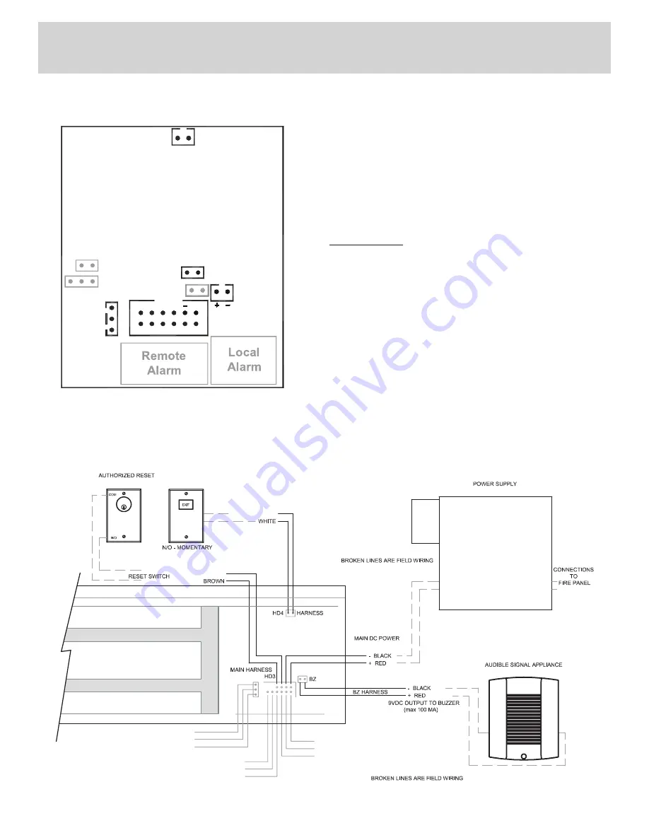
Circuit Board Connections
HD4:
N/O momentary request to exit switch
(7 second built in release)
BZ:
9VDC output to Buzzer max 100mA
HD2:
Same as Remote A below
JP2:
Jumper off to enable low voltage detection
(factory default)
Jumper on to disable low voltage detection
HD3 Main Harness
RST:
Connect the brown and brown/white leads to
reset switch
- DC:
DC power wires; black is negative (-) and
Red is positive (+)
Remote A
Purple is common (C)
Orange is normally closed (NC)
Blue is normally open (NO)
Local:
Grey is common (C)
Green is normally open (NO)
Pink is normally closed (NC)
(ORDER SEPARATELY)
RCI 960 MO RECOMMENDED
(ORDER SEPARATELY)
OPTIONAL
REQUEST TO EXIT SWITCH
RCI 970 0R 975 RECOMMENDED
NC PINK
NO GREEN
LOCAL
COMMON GREY
AUDIO SELECT – SOUND PATTERNS
7, 8, OR 9 ONLY
FOR RCI MODEL 914
PER CODE
12VDC to 24VDC
PURPLE COMMON
HD2
REMOTE A
ORANGE NC
BLUE NO
PURPLE COMMON
HD2 HARNESS - REMOTE B ORANGE NC
BLUE NO
WHITE
/
BLACK
BROWN
/
WHITE
Wiring Diagram
Diagram reflects status with power on and door opened.
A mechanical latching device is recommended in conjunction with the Early Warning 8310 to maintain security during a power failure.


