
F
C
G
G
A
M
B K
E
X
R
D
F
C
L
M
C
L
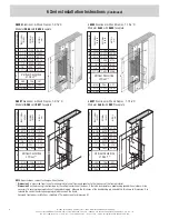
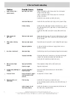
S6507
Aluminum & Wood Frames, 1-3/16" D
Modular
AS65
with
B607
faceplate
A
1-1/4
1.250
31.75
B
6-7/8
6.875
174.63
C
3-3/8
3.375
85.73
D
1-3/16
1.188
30.16
E
3/8
0.375
9.53
F
1/8*
.125*
3.18*
G
1-11/16
1.688
42.86
Vertical
Vertical
Vertical
X
C/L
C/L
C/L
Door
Door
Door
R
5/32
.156
3.97
K
6-1/8
6.125
155.58
M
12-24
†
—
—
MEASUREMENT
FRACTIONAL
INCHES
DECIMAL
INCHES
METRIC
mm
Vertical Centerline
of Door**
6 Series Installation Instructions
(Continued)
X
E
K
B
R
M
F
D
G
G
C
A
M
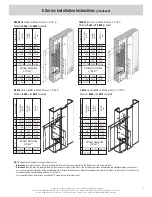
MEASUREMENT
FRACTIONAL
INCHES
DECIMAL
INCHES
METRIC
mm
A
1-1/8
1.125
28.58
B
5-7/8
5.875
149.23
C
3-3/8
3.375
85.73
D
1-3/16
1.188
30.16
E
1/4
0.250
6.35
F
1/8*
.125*
3.18*
G
1-11/16
1.688
42.86
Vertical
Vertical
Vertical
X
Door
Door
Door
R
5/32
.156
3.97
K
5-3/8
5.375
136.53
M
12-24
†
—
—
Vertical Centerline
of Door**
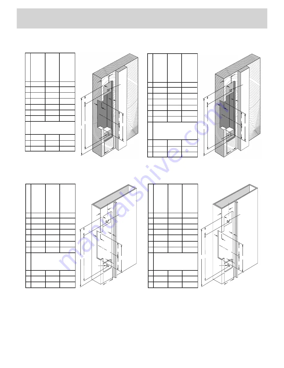
L6505
Aluminum & Wood Frames, 1-1/16" D
Modular
AL65
with
B605
faceplate
X
E
K
B
R
M
F
D
G
G
C
A
M
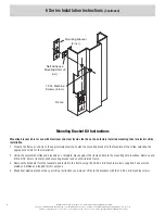
MEASUREMENT
FRACTIONAL
INCHES
DECIMAL
INCHES
METRIC
mm
A
1-1/8
1.125
28.58
B
5-7/8
5.875
149.23
C
3-3/8
3.375
85.73
D
1-3/32
1.094
27.78
E
1/4
0.250
6.35
F
1/8*
.125*
3.18*
G
1-11/16
1.688
42.86
Vertical
Vertical
Vertical
X
C/L
C/L
C/L
Door
Door
Door
R
5/32
.156
3.97
K
5-3/8
5.375
136.53
M
12-24
†
—
—
Vertical Centerline
of Door**
F
C
G
G
A
M
B K
E
X
R
D
F
C
L
M
C
L
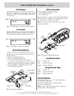
L6507
Aluminum & Wood Frames, 1-1/16" D
Modular
AL65
with
B607
faceplate
A
1-1/4
1.250
31.75
B
6-7/8
6.875
174.63
C
3-3/8
3.375
85.73
D
1-3/32
1.094
27.78
E
3/8
0.375
9.53
F
1/8*
.125*
3.18*
G
1-11/16
1.688
42.86
Vertical
Vertical
Vertical
X
C/L
C/L
C/L
Door
Door
Door
R
5/32
.156
3.97
K
6-1/8
6.125
155.58
M
12-24
†
—
—
MEASUREMENT
FRACTIONAL
INCHES
DECIMAL
INCHES
METRIC
mm
Vertical Centerline
of Door**
NOTE
: Specifications subject to change without notice.
*
Dimension F
is measured from face of mounting tab to face of frame and equates to the thickness of the frame material.
**
Dimension X
on the drawing is determined by the vertical centerline of the door. If the latch incorporates a deadlocking pin additional steps will be
necessary to ensure proper operation of the deadlocking pin. Measure the thickness of the deadlocking pin and add this thickness to Dimension X to
relocate the vertical centerline an appropriate distance on the frame.
†
For wood frame door installations, substitute #12 wood screws for dimension M.
©2008 RUTHERFORD CONTROLS INT’L CORP. WWW.RUTHERFORDCONTROLS.COM
USA: 2697 INTERNATIONAL PARKWAY, PKWY 5, VIRGINIA BEACH, VA 23452 • CANADA: 210 SHEARSON CRESCENT, CAMBRIDGE, ON N1T 1J6
PHONE • 1.800.265.6630 • 519.621.7651 • FAX: 1.800.482.9795 • 519.621.7939 • E-MAIL: SALES@RUTHERFORDCONTROLS.COM
2
S6505
Aluminum & Wood Frames, 1-3/16" D
Modular
AS65
with
B605
faceplate


