
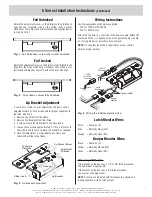
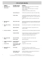
Fail Unlocked
Rotate the adjustment screw so the dimple is fully rotated to
opposite the faceplate side of the strike (fully counter
clockwise). Your strike is now fail unlocked and requires power
to lock. See Fig. 1.
Fail Locked
Rotate the adjustment screw so the dimple is fully rotated to the
faceplate side of the strike (fully clockwise). Your strike is now
fail locked and requires power to unlock the door. See Fig 2.
Lip Bracket Adjustment
If your door or latch is out of adjustment, the insert can be
adjusted forward or back as required for proper alignment to
the latch. See Fig. 3
1. Remove the strike from the frame.
2. Remove the faceplate from the strike.
3. 2 screws secure the lip bracket to the main insert.
4. Loosen these screws approximately 1-1/2 to 2 full turns to
allow the insert to move forward or backward as required.
5. Once the adjustment is made tighten all screws and
reinstall the strike in the frame.
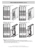
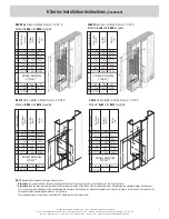
6 Series Installation Instructions
(Continued)
Lip Bracket Screw
Faceplate
Removed
Adjustment
Direction
Lip Bracket
Strike Insert
Keeper
Fig. 1
Fail Unlocked = screw fully counter clockwise
Fig. 2
Fail Locked = screw fully clockwise
Fig. 3
Lip bracket adjustment
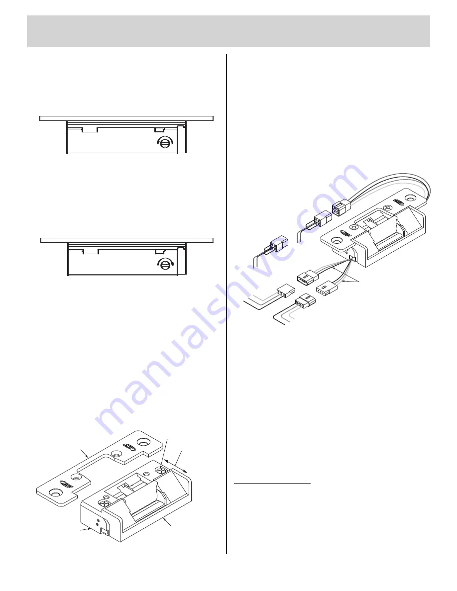
Wiring Instructions
Use the appropriate wire harness supplied.
12V for 12VDC & 12-24VAC
24V for 24VDC only
Attach the red wire to (+) positive of the power supply. Attach the
black wire to the (–) negative of the of the power supply (see Fig.
4). If using AC power, polarity is not observed.
NOTE
: If a suppression diode is required for access control,
observe proper polarity.
Latch Monitor Wires
Black
= Common (C)
Blue
= Normally Close (NC)
Orange
= Normally Open (NO)
Keeper Monitor Wires
Black
= Common (C)
Yellow
= Normally Closed (NC)
Green
= Normally Open (NO)
When using LMKM option:
If the lockset on the door has a 1/2" or 5/8" latch projection,
The L65 model is appropriate.
If the lockset on the door has a 3/4" latch projection,
you must use the S65 model.
NOTE
: Contacts are indicated with the keeper in a closed and
locked condition, with no latch present.
Red
Black
Optional LMKM
Latch
Monitor
Keeper
Monitor
NC
C
NO
NO
C
NC
24VDC
Terminal
+–
12VDC
12-24VAC
Terminal
+–
Red
Black
Fig. 4
Wiring the 6 Series electric strike
©2008 RUTHERFORD CONTROLS INT’L CORP. WWW.RUTHERFORDCONTROLS.COM
USA: 2697 INTERNATIONAL PARKWAY, PKWY 5, VIRGINIA BEACH, VA 23452 • CANADA: 210 SHEARSON CRESCENT, CAMBRIDGE, ON N1T 1J6
PHONE • 1.800.265.6630 • 519.621.7651 • FAX: 1.800.482.9795 • 519.621.7939 • E-MAIL: SALES@RUTHERFORDCONTROLS.COM
5


