background image

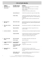
6 Series Troubleshooting

Latch or keeper are not

functioning properly

Confirm that the keeper is closing properly and that the lever in

the strike cavity is operating freely.

Solution

Possible Causes

Problem

Strike will not lock or

unlock properly

No power to the insert

Using a multimeter, confirm that you have the correct output

voltage at the power supply.

Using a multimeter, confirm that you have the correct input

voltage at the strike.

Confirm that all connections are tight and secure.

Incorrect voltage used

Confirm that the insert and power supply are the proper voltage.

Strike is binding

Confirm that the strike keeper functions when the door is open. If

the strike operates correctly, adjust door or strike to eliminate any

backpressure.

Confirm that the strike cavity depth is compatible with the lock

set.

Strike releases but 

won’t buzz

Improper power supply

Replace the power supply with a correct voltage AC power supply,

and the 12V connector. If this cannot be done, a DC piezo buzzer

can be installed.

Strike makes a buzzing

sound

Improper power supply

Replace the power supply with a correct voltage DC power supply.

Insert has a burnt smell

Improper voltage

Confirm that you have the correct output voltage at the power supply.

Improper application

A strike connected to an AC power supply will buzz unless a

rectifier is installed.

Improper installation

Confirm that the correct connector was used when installing the

strike 12V for 12VDC & 12-24VAC, 24V for 24VDC only.

Confirm that all connections are tight and secure.

Mortise lock not dead

latching

Improper Installation

Check alignment of dead latch and lip bracket ramp.

Door has sagged

Adjust door alignment.

Cylindrical deadlatching not

working

Improper Installation /

Door has warped

Adjust the strike horizontal adjustment. (See Installation

Instructions).

Door won’t latch

Door has warped or sagged

creating excessive back

pressure

Re-align door in frame or replace.

Monitor switch is not

functioning

Short in wiring

Confirm that all connections are tight and secure.

Using a multimeter confirm continuity of the N/O & N/C sides of

the switch.

1.

2.

3.

4.

5.

6.

7.

8.

©2008 RUTHERFORD CONTROLS INT’L CORP. WWW.RUTHERFORDCONTROLS.COM

USA: 2697 INTERNATIONAL PARKWAY, PKWY 5, VIRGINIA BEACH, VA 23452 • CANADA: 210 SHEARSON CRESCENT, CAMBRIDGE, ON  N1T 1J6 

PHONE • 1.800.265.6630 • 519.621.7651 • FAX: 1.800.482.9795 • 519.621.7939 • E-MAIL: SALES@RUTHERFORDCONTROLS.COM 

6

Summary of Contents for L65 Series

Page 1: ... I O N Electric Strikes 6 Series Instructions E K B A F M G C G D R X C L C L M L6504 Aluminum Wood Frames 1 1 16 D Modular AL65 with B604 faceplate MEASUREMENT FRACTIONAL INCHES DECIMAL INCHES METRIC mm A 1 1 4 1 250 31 75 B 4 7 8 4 875 123 83 C 3 3 8 3 375 85 73 D 1 3 32 1 094 27 78 E 3 8 375 9 53 F 1 8 125 3 18 G 1 11 16 1 688 42 86 Vertical Vertical Vertical X C L C L C L Door Door Door R 5 32...

Page 2: ...enterline of Door F C G G A M B K E X R D F C L M C L L6507 Aluminum Wood Frames 1 1 16 D Modular AL65 with B607 faceplate A 1 1 4 1 250 31 75 B 6 7 8 6 875 174 63 C 3 3 8 3 375 85 73 D 1 3 32 1 094 27 78 E 3 8 0 375 9 53 F 1 8 125 3 18 G 1 11 16 1 688 42 86 Vertical Vertical Vertical X C L C L C L Door Door Door R 5 32 156 3 97 K 6 1 8 6 125 155 58 M 12 24 MEASUREMENT FRACTIONAL INCHES DECIMAL IN...

Page 3: ...or Door Door R 5 32 156 3 97 K 7 7 16 7 438 188 91 M 12 24 Vertical Centerline of Door X E K B R M F D G G C A M L6508 Aluminum Wood Frames 1 1 16 D Modular AL65 with B608 faceplate MEASUREMENT FRACTIONAL INCHES DECIMAL INCHES METRIC mm A 1 7 16 1 438 36 51 B 7 15 16 7 938 201 61 C 3 3 8 3 375 85 73 D 1 3 32 1 094 27 78 E 1 4 0 250 6 35 F 1 8 125 3 18 G 1 11 16 1 688 42 86 Vertical Vertical Vertic...

Page 4: ...ory installed mounting tabs for electric strike installation 1 Prepare the frame as shown in the approximate drawing Fasten the mounting bracket to the faceplate of the strike selecting the appropriate shims for the installation 2 Using the assembled strike and brackets as a template place against the frame and mark the mounting hole locations Remove and drill a 3 16 hole in frame for each mountin...

Page 5: ...cked screw fully clockwise Fig 3 Lip bracket adjustment Wiring Instructions Use the appropriate wire harness supplied 12V for 12VDC 12 24VAC 24V for 24VDC only Attach the red wire to positive of the power supply Attach the black wire to the negative of the of the power supply see Fig 4 If using AC power polarity is not observed NOTE If a suppression diode is required for access control observe pro...

Page 6: ...rrect voltage DC power supply Insert has a burnt smell Improper voltage Confirm that you have the correct output voltage at the power supply Improper application A strike connected to an AC power supply will buzz unless a rectifier is installed Improper installation Confirm that the correct connector was used when installing the strike 12V for 12VDC 12 24VAC 24V for 24VDC only Confirm that all con...

Reviews: