36
12
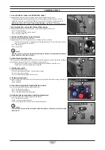
6. Side brushes lifting/lowering knobs (left side brush optional)
During the transfer or when the machine is at rest, lift the side brush as follows:
•
To lift the brush place the knob in position “S”.
During the work, lower the side brush as follows:
•
Place the knob on position “A” to lower the brush.
Pos. A = brushes lowered, Pos. S = brushes lifted.
!
Caution!
When the sweeper is at rest, the side brushes must always be lifted above the ground to avoid
deformations (bending of the brush’s bristles).
6a. Side brushes adjusting screws (side brush optional)
If the side brushes are worn adjust it with the properly screws.
The side brushes should just touch the fl oor, leaving a “T” trace (fi g.6).
•
Loosen the screws and move it up or down through the slotted hole to adjust the trace.
•
Tighten the screws when the adjusting is completed.
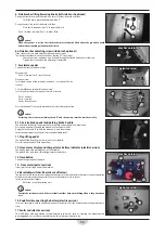
7. Accelerator pedal
Controls the transfer of the machine.
Petrol version:
Pos. A = forward, Pos. R = back (reverse).
Electric version:
Select the direction of the sweeper (see point 8). Act on pedal for the
transfer.
8. Forward/Reverse selector (electric version)
Selects the direction of the sweeper forward or reverse.
Pos. 0 = neutral.
Pos. A = forward.
Pos. R = back (reverse).
Press on the pedal 7 in order to proceed to the selected drive direction.
!
Caution!
At start-up, the selector must always be on “0” and the operator must be seated correctly.
9-10. Service brake pedal and parking brake handle
The pedal and lock ball grip operate the service brake and parking brake respectively.
Press down on pedal 9 to apply the brake block to the rear wheels.
Apply the lock handle 10 to hold the brake on to park the machine.
For brake adjustment see chapter “Service and parking brakes”.
11. Flap lifting pedal
The pedal lift the front fl ap in order to pass it over rubbish.
Press this pedal down to lift the front fl ap.
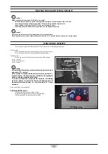
12. Hour-meter display and charge status battery indicator (electric version)
The display shows the working hours of the machine.
The graded Leds scale shows the charge status of the battery.
13. Horn button
Controls the operation of the horn.
14. Hour meter (petrol version)
It indicates the starting hours of the machine.
15. Resettable switches (thermic cut off valves)
The thermic cut off valves serve as safeguard the electric system and the brush motors, incorrect operation
of the brush motors or by the operator can cause the thermic valves to cut out.
In this case proceed as follows:
•
Reset the cut out by pressing on it.
!
Caution!
Contact the assistance centre if the resettable switches keep on switching off once they have been
reset.
16. Knob for disconnecting the battery (electric version)
In case of emergency push the knob to disconnect the battery. Pull the knob to restore the normal opera-
ting.
17. Faults Led (electric version)
The led fl ashes when operations are performed incorrectly , such as: starting the machine with
gear engaged, etc., or there is a problem on the electronic control unit.
7
electric version
electric version
7
A
A
R
R
petrol version
petrol version
9
11
8
A
A
R
R
0
0
10
13
14
15
petrol version
petrol version
12
13
15
16
17
electric version
electric version
6
A
A
SS
6a

