


19
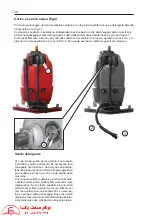
CONTROLS (FIG.3)
1)
BRUSH SUPPORT PRESSURE TRIMMER
2)
PARKING BRAKE LEVER
3)
ACCELLERATOR AND REVERSE PEDAL
4) BRAKE
PEDAL
5)
SOLUTION TAP ON/OFF LEVER
6)
SUCTION CONTROL BUTTON
7)
STARTING KEY SWITCH
8)
SOLUTION ON INDICATOR LIGHT (GREEN)
9) HORN
10)
DISPLAY AND FUNCTION SWITCH
11) -
12) SPEED
SWITCH
13)
BRUSH CONTROL BUTTON
14) SOLUTION
TANK
CAP
15)
EMERGENCY STOP BUTTON
16)
FORWARD AND REVERSE TRAVEL JOYSTICK
Summary of Contents for JUMBO 1002 RN
Page 2: ...RCM ...
Page 3: ...ITA MANUALE USO E MANUTENZIONE GB INSTRUCTION AND MAINTENANCE HANDBOOK ...
Page 64: ...64 IMPIANTO ELETTRICO LINEA CRUSCOTTO FIG 15 ELECTRIC SYSTEM DASHBOARD LINE ...
Page 66: ...66 IMPIANTO ELETTRICO LINEA CENTRALE CRUSCOTTO FIG 15A ELECTRIC SYSTEM DASHBOARD MAIN LINE ...
Page 68: ...68 IMPIANTO ELETTRICO LINEA POSTERIORE FIG 15B ELECTRIC SYSTEM REAR LINE ...
Page 70: ...70 IMPIANTO ELETTRICO LINEA ATTUATORI PEDANA FIG 15C ELECTRIC SYSTEM ACTUATORS LINE BOARD ...
Page 72: ...72 1 FUSIBILI FIG 16 1 FUSIBILE GENERALE 150A ...


