


21
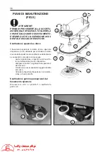
DESCRIPTION OF CONTROLS (FIG.3)
1) BRUSH SUPPORT PRESSURE TRIMMER
Used to adjust the pressure the brushes apply to the fl oor. Turn clockwise to increase the total pressure
applied to the fl oor.
2)
PARKING BRAKE LEVER
Used to lock the brake pedal in and release it from the parking position.
3)
ACCELERATOR AND REVERSE PEDAL
Controls the scrubber/drier’s speed in forward or reverse travel.
4) BRAKE
PEDAL
Controls the service and parking brake. The pedal acts directly on the brakes on the front wheels.
5)
SOLUTION TAP ON/OFF LEVER
Turns on or off and regulates the fl ow of solution onto the brushes.
6)
SUCTION CONTROL BUTTON
Controls operation of the suction motor.
“stop” position: motor off
“fan” position: motor operating
7) STARTING
KEY-SWITCH
Controls activation of all the electric controls.
“0” position: controls off
“1” position: controls on
8)
SOLUTION ON INDICATOR LIGHT (GREEN)
When the light is on, the solution tap is turned on.
9) HORN
Controls operation of the horn.
10) DISPLAY AND FUNCTION SWITCH
The display provides information about the status of the battery and indicates alarms (see DESCRIPTION OF ALARMS).
Push on the function switch to see the following information:
- THE WORKED HOURS OF THE MACHINE
- THE WORKED HOURS OF THE BRUSHES
- THE HOURS LEFT TO THE NEXT MAINTENANCE VISIT
Note: see also the use and maintenance manual of the electronic control unit - Penny & Giles “Trio”
Summary of Contents for JUMBO 1002 RN
Page 2: ...RCM ...
Page 3: ...ITA MANUALE USO E MANUTENZIONE GB INSTRUCTION AND MAINTENANCE HANDBOOK ...
Page 64: ...64 IMPIANTO ELETTRICO LINEA CRUSCOTTO FIG 15 ELECTRIC SYSTEM DASHBOARD LINE ...
Page 66: ...66 IMPIANTO ELETTRICO LINEA CENTRALE CRUSCOTTO FIG 15A ELECTRIC SYSTEM DASHBOARD MAIN LINE ...
Page 68: ...68 IMPIANTO ELETTRICO LINEA POSTERIORE FIG 15B ELECTRIC SYSTEM REAR LINE ...
Page 70: ...70 IMPIANTO ELETTRICO LINEA ATTUATORI PEDANA FIG 15C ELECTRIC SYSTEM ACTUATORS LINE BOARD ...
Page 72: ...72 1 FUSIBILI FIG 16 1 FUSIBILE GENERALE 150A ...


