29
USING THE SCRUBBER/DRIER
Necessary precautions
1. The scrubber/drier must only be used by competent, responsible persons.
2. When the scrubber/drier is left unattended, remove the key 7 (fi g. 3) and stop it moving by engaging
and locking the parking brake (see BRAKES).
3. When
the
fl oor-washer is not in use, the brushes must be raised to avoid deformation of the bristles.
4. Never stop the machine on slopes.
CAUTION !
BEFORE USING THE SCRUBBER/DRIER, CHECK THE LEVEL OF FLUID IN THE
BATTERY.
Instructions for starting up the scrubber/drier
Points for scrubber start-up
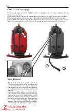
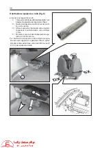
1. Make sure that the recovered water tank 2 (see illustration below) is empty.
2. Fill the solution tank 1 (see illustration below).
3. Check that the brake is released.
4. Insert the key 7 (fi g. 3) in the general control panel and turn it clockwise (this will supply power to
the general control system).
5. Switch on the suction by pressing the button 6 (fi g. 3).
6. Switch on the brush rotation by pressing the button 13 (fi g. 3).
7. Turn on the solution tap using the lever 5 (fi g. 3).
CAUTION!
AS ALREADY MENTIONED BUTTON 13 (FIG. 3), AS WELL AS STARTING ROTATION
OF THE BRUSHES, WHEN THE TRAVEL JOYSTICK 16 (FIG. 3) IS OPERATED, IF THE
FORWARD TRAVEL PEDAL HAS NOT BEEN PRESSED WITHIN SIX SECONDS, THE
BRUSHES ARE RAISED AUTOMATICALLY AND THE PEDAL HAS TO BE PRESSED
AGAIN TO LOWER THEM.
8. To start travel and obtain the desired speed, press the accelerator pedal 3 (fi g. 3) gradually.
CAUTION!
THE SCRUBBER/DRIER ONLY OPERATES WITH THE DRIVER PROPERLY
SEATED IN THE DRIVING SEAT AND THE EMERGENCY BUTTON DISENGAGED.
BEFORE STARTING TO WORK, THE MACHINE’S FUNCTIONS ARE DELAYED BY
THE PROGRAM.
Summary of Contents for JUMBO 1002 RN
Page 2: ...RCM ...
Page 3: ...ITA MANUALE USO E MANUTENZIONE GB INSTRUCTION AND MAINTENANCE HANDBOOK ...
Page 64: ...64 IMPIANTO ELETTRICO LINEA CRUSCOTTO FIG 15 ELECTRIC SYSTEM DASHBOARD LINE ...
Page 66: ...66 IMPIANTO ELETTRICO LINEA CENTRALE CRUSCOTTO FIG 15A ELECTRIC SYSTEM DASHBOARD MAIN LINE ...
Page 68: ...68 IMPIANTO ELETTRICO LINEA POSTERIORE FIG 15B ELECTRIC SYSTEM REAR LINE ...
Page 70: ...70 IMPIANTO ELETTRICO LINEA ATTUATORI PEDANA FIG 15C ELECTRIC SYSTEM ACTUATORS LINE BOARD ...
Page 72: ...72 1 FUSIBILI FIG 16 1 FUSIBILE GENERALE 150A ...


