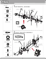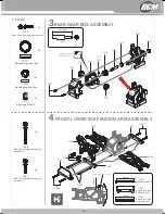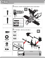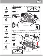
background image

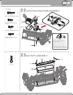
22

.SERVO\

RECEIVER 

ESC\

ASSEMBLY

23

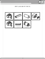
.BATTERY ASSEMBLY

7233

7283
7287

7245

7250

7246

Receiver

90

. 0

Installment of the servo arm.

2.Adjust the servo in the middle, then 

adjust the steering system to the same 

situation. The servo rocker should keep an 

angle of 90° ±5°with the horizon

1.Press the F crank set into servo 

wheel(The tooth profile of the crank set 

should aim at that of servo)

3.Press the servo rocker into the out tooth 

of the crank set(The tooth profile of the 

servo rocker should aim at the tooth profile 

of the crank set), finally lock the screw.

7274

7284
7288

7211

7274

x4

7252

x1

7245

x1

7250

x1

7246

x2

7274

7252

7211

7286

7286

7286

M3X12 Pan Self-tapping Screw Set

M3X8 Flat Head Self-tapping 

Screw Set

M3X6 Pan Self-tapping Screw Set

M3X10 Flat Head Self-tapping 

Screw Set

R

-

Pin


Set

Sponge double-

sided tape

Sponge double-

sided tape

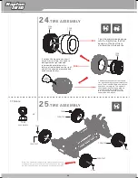
25

1:1 Scale

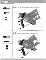
20

.

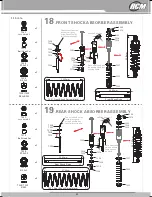
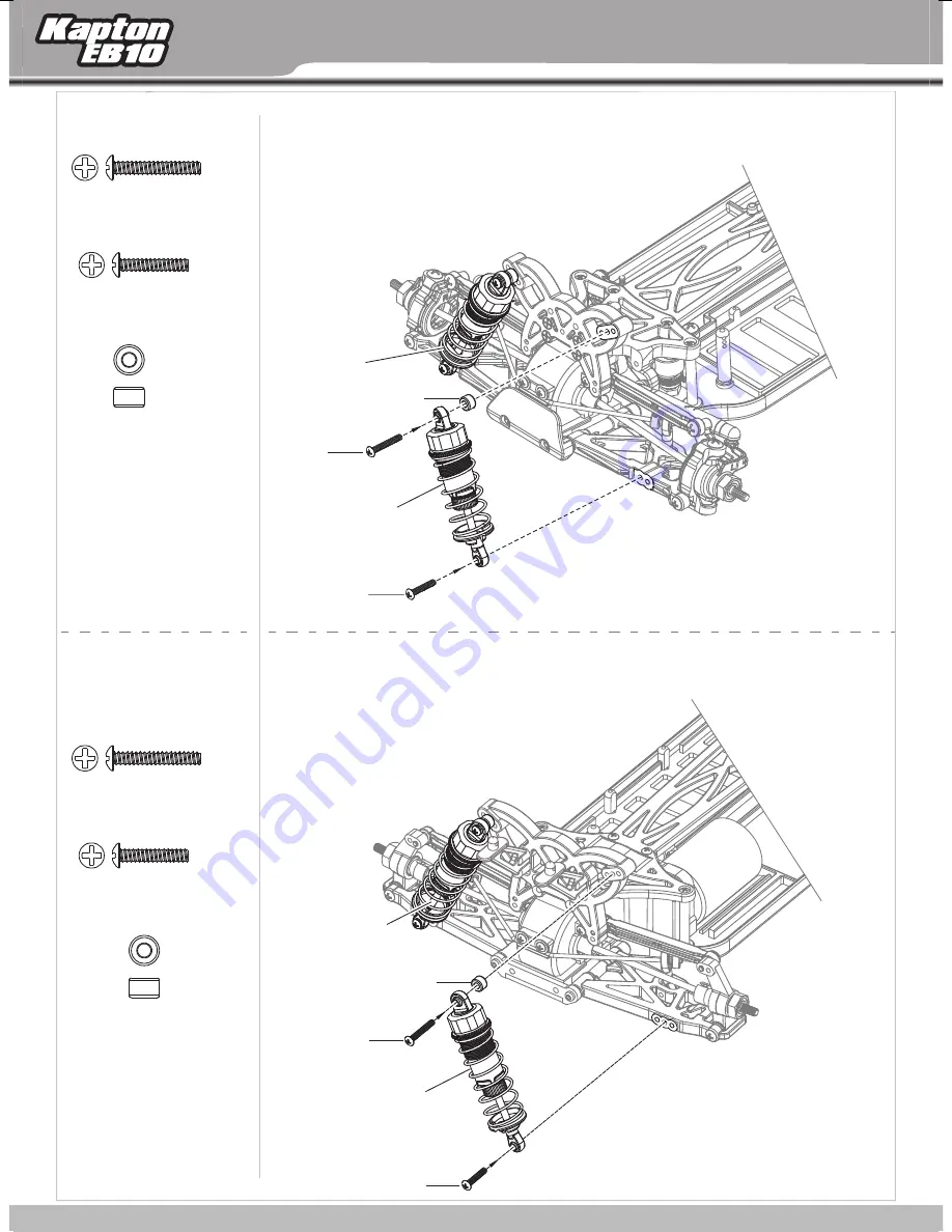
SHOCK ABSORBER ASSEMBLY


FRONT 

21

.REAR SHOCK ABSORBER ASSEMBLY


7255

7254

7230

x2

7255

x2

7254

x2

7230

x2

7255

x2

7254

x2

7230

7219

7219

7255

7230

7254

7220

7220

M3X20 Pan Self-tapping Screw Set

M3X16 Pan Self-tapping Screw Set

M3X20 Pan Self-tapping Screw Set

M3X16 Pan Self-tapping Screw Set

Shock


End


Set


Φ

7x4

.

5

Shock


End


Set


Φ

7x4

.

5

B

-

10E

24

1:1 Scale

23

22

manual_kapton.indd   22

07/10/13   19:57

Summary of Contents for Kapton EB10

Page 1: ...place the spare parts please keep and take it for reference The user who is not familar with the assembling please contact with the wholesaler nominated model shops and the Special after sale service outlets This manual expatiate the structure of the model In order to better B 10E S pecifications Length 417m m Width 250 252m m Height 151m m Wheel Base 290m m Gear Ratio 9 47 1 Tire Type Φ87x34m m F...

Page 2: ...in t g h t e op qualit a y n b d es s t ervice Throug a h ttendin t g h c e ompetition a s n r d epeate t d estin t g h p e roducts constantl e y nhancin o g u e r xperience the f n urthe i r mprovin t g h d e esig a n n q d ualit c y ontrol O nl f y or showin t g h g e rea p t erformanc p e roducts Thi m s anua i l ncludin a g l t l h i e mportan m t atte b r efor o e perating th c e a W r a e dv...

Page 3: ...n body contact activities of the parts before cut off the power supply 7 During the operation if foreign matter or liquid get into eyes please timely with plenty of water flush eyes and immediately consulting professional doctor As the body is injured please seek immediate medical attention 8 Keep out of the reach of children this is not toy strongly suggest adult supervision 9 Placed in ventilate...

Page 4: ...2 5 2 EB10 5000 mAh 30C Li po battery EB10 4 ...

Page 5: ... 000001 00 07 Hobby Knife 6X0 000028 00 00 Wire Cutters 6Y7 000001 00 00 Needle Nose Pliers 6T4 000096 00 00 Reamer Recommended maintenance tools not included 8PT 040001 71 00 Symbols used throughout the instruction manual Assemble both L R sides Assemble both F R sides Apply CA glue not included All kinds of grease not included on the products 55 ...

Page 6: ...r 2 3 4 1 5 6 8 9 10 7 11 1 2 3 4 5 6 7 8 9 10 11 12 13 12 Tail 13 Brushless Motor Brushless ESC Receiver Servo Gear Box Front Tire Battery Drive Shaft Rear Tire Locknut Wheel Hub Drive Shaft B 10E 6 EB10 Brushless Car 6 ...

Page 7: ... 8 9 10 7 11 12 Tail 13 Brushed Motor Brushed ESC Receiver Servo Gear Box Front Tire Battery Drive Shaft Rear Tire Locknut Wheel Hub Drive Shaft B 10E Brushed Car 1 2 3 4 5 6 7 8 9 10 11 12 13 7 EB10 Brushed Car 7 ...

Page 8: ...TLET PLUG FROM CHARGER LiPo BATTERIES 9 CHA R G IN G T HE B A T T E R Y P A CK 1 2 3 A Once the battery ready to be charged first plug the AC quick charger into the outlet of AC power source and then connect the battery input output harness to the charger B Continued to monitor the battery as it is being charged As soon as the battery is fully charged disconnect the battery from the charger plug O...

Page 9: ... If long time idle do not leave the battery in the remote control Racing Operation Steps Cover the cap of the radio Properly installed antenna tube put the battery into the battery tank cover the battery box Adjust the throttle steering vernier adjustment knob button to median MID direction big small rudder Angle knob button to 120 Be sure to first open the remote control power and then open the m...

Page 10: ...sting the diversion of the car please keep the front wheel hang in the air Throttle operation 1 Slowly press the throttle operation lever the cars will be slow to overtake 2 When the throttle lever to push up the car will be braking action when making brake median brake action the car will make back action when there is not consistent please strike on the remote control of TH oil Door and rudder s...

Page 11: ... throttle only steering Motor keeps running Gear mesh is too tight Battery is discharged Check for loose wires dead radio batteries or loose crystals Check motor capacitors losse wires or crystals Check throttle steering reversing switches on transmitter Plug servo into ESC unit Free up steering linkage Replace servo Plug motor in Replace motor A T L function works turn off the vehicle first and f...

Page 12: ...60 x2 7251 x2 7271 7270 x2 x1 7260 x1 7272 7172 7279 1 1 7175 28mm M2x10 Socket Cap Screw M3X10 Pan Self tapping Screw Set Set Screw M4x4 φ10xφ5 5x0 3 Washers φ8xφ5 1x0 3 Washers E button φ2 5x0 4 Ball bearing φ15x10x4 Ball bearing φ10x5x4 E button φ2 5x0 4 Add appropriate amount of oil Add appropriate amount of oil Add appropriate amount of oil Add appropriate amount of oil Put a little screw glu...

Page 13: ...47 1 1 7175 26 2mm 7176 7175 7272 7177 7177 7251 7271 7271 7270 7270 7170 7175 M3X10 Pan Self tapping Screw Set M3X12 Flat Head Self tapping Screw Set M3X20 Flat Head Self tapping Screw Set 1 1 Scale Ball bearing φ15x10x4 Ball bearing φ10x5x4 E button φ2 5x0 4 Add appropriate amount of oil Susp Arm Hinge Pin Brace front 3x30mm Hinge Pin Susp Arm Hinge Pin Brace front 15 with a gap of 0 10mm 13 ...

Page 14: ...4 9mm 50 8mm 0 10mm 7181 7181 7182 7183 7247 7184 7247 7184 7254 1 1 79 70mm M3X12 Flat Head Self tapping Screw Set M3X16 Pan Self tapping Screw Set M3x4 1 Screw rod Steering Ball Screws φ4 7 M3 1 1 Scale Ball bearing φ15x10x4 Ball bearing φ10x5x4 φ2x11 Pin Set φ2x10 Pin Set φ2x9 7 Pin Set Susp Arm Hinge Pin Brace rear 3x30mm Hinge Pin Susp Arm Hinge Pin Brace rear Left right Add appropriate amoun...

Page 15: ...1 3mm 1mm 1 1 7270 7190 7270 7189 7190 7278 7188 7268 Set Screw M3x3 M3X6 Pan Self tapping Screw Set M3X14 Pan Self tapping Screw Set Set Screw M3x10 Set Screw M3x3 M3X6 Pan Self tapping Screw Set M3X14 Pan Self tapping Screw Set φ8xφ3 2x0 5 Washers φ8xφ3 2x0 5 Washers Φ7 5xΦ5 1x2 1 Rear Wheel Shaft Washers 1 1 Scale Front Sway Bar right Left Rear Sway Bar Set Screw M3x10 Front Lower Suspension Pi...

Page 16: ...rods Different driving feeling appears with different pull rod length You can choose appropriate pull rods based on the field The front up pull rod 3 selective use The front up pull rod 2 standard Use The front up pull rod 1 selective use The rear up pull rod 3 selective use The up pull rod 2 standard Use rear The up pull rod 1 selective use rear The camber of tire can be changed when you adjust t...

Page 17: ...249 7198 7246 x4 7249 x4 7246 7200 x2 7199 x2 M3X8 Flat Head Screw Set M3X10 Flat Head Self tapping Screw Set Aluminium strut Servo Saver Post 1 1 Scale Add appropriate amount of oil Add appropriate amount of oil Hexagon of the pivoting point should align to that of baseboard 19 17 ...

Page 18: ... 7268 7204 1 1 6 00mm 7204 7206 7268 Set Screw M4x4 M3X8 Pan Head Screw Set Lock Nut M4 M3X8 Flat Head Screw Set M3X8 Flat Head Self tapping Screw Set M3X10 Pan Self tapping Screw Set Ball bearing φ15x10x4 Aluminium strut 1 1 Scale Adjusting spring Φ7 6xΦ1 4x14 5 The screw should be locked in the planimetric position of shaft Put a little screw glue Put a little screw glue Put a little screw glue ...

Page 19: ...f tapping Screw Set M3X8 Flat Head Self tapping Screw Set Steering Ball Screws φ4 7 M3 φ8xφ5 1x0 3 Washers 1 1 Scale Add appropriate amount of oil Put a little screw glue The screw should be locked in the planimetric position of shaft The toe in angle of the front tire can be changed when you adjust the length of the pull rods Different driving feeling appears with different steering pull rod leng...

Page 20: ...51 x5 x8 7257 7251 7251 7257 7217 7257 7218 7251 7197 M3x4 8 Screw rod M3X10 Pan Self tapping Screw Set M3X10 Pan Head Screw Set Ball bearing φ8x5x2 5 1 1 Scale Steering Servo Turnbuckle Add appropriate amount of oil Add appropriate amount of oil Put a little screw glue Put a little screw glue B 10E 22 20 ...

Page 21: ... Nut M2 5 Lock Nut M2 5 Ball Head Set Ball Head Set Rear Shock Rods Front Shock Rods 7221 Front Shock Spring black 7221 Rear Shock Spring black 1 1 Scale 7228 7272 7228 7229 7228 7228 7261 7223 7228 7229 7228 Oil 7228 7226 7230 7273 7232 7273 7230 7225 7227 24 3mm 91 8mm The nut should not be locked too tightly or the E buckle may fall of after extrusion Add the Shock oil Move slowly and wait the ...

Page 22: ...0 x2 7255 x2 7254 x2 7230 x2 7255 x2 7254 x2 7230 7219 7219 7255 7230 7254 7220 7220 M3X20 Pan Self tapping Screw Set M3X16 Pan Self tapping Screw Set M3X20 Pan Self tapping Screw Set M3X16 Pan Self tapping Screw Set Shock End Set Φ7x4 5 Shock End Set Φ7x4 5 B 10E 24 1 1 Scale 22 ...

Page 23: ...rofile of the crank set should aim at that of servo 3 Press the servo rocker into the out tooth of the crank set The tooth profile of the servo rocker should aim at the tooth profile of the crank set finally lock the screw 7274 7284 7288 7211 7274 x4 7252 x1 7245 x1 7250 x1 7246 x2 7274 7252 7211 7286 7286 7286 M3X12 Pan Self tapping Screw Set M3X8 Flat Head Self tapping Screw Set M3X6 Pan Self ta...

Page 24: ...ng to the texture of the tire because the right and left tire should be installed and used symmetrically 3 Widen the touch part of the tire and rim and then drop in the universal glue note The air should flow well when you use the universal glue The operator should wear respirator goggle and gloves to avoid the accident The juveniles should operate under the supervise of the adults Note You need t...

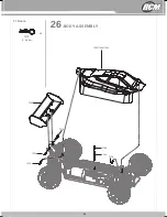
Page 25: ...26 BODY ASSEMBLY 7243 7239 7240 7241 7274 7274 7274 7274 7238 7238 7274 x4 R Pin Set 27 1 1 Scale 25 ...

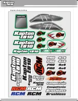
Page 26: ...B 10E 28 Diagram of bodyshell tags Kapton EB10 RCM 200 x 155 mm http www rcmitico es 26 ...

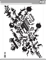
Page 27: ...81 7246 7247 7245 7265 7265 7265 7265 7213 7213 7212 7212 7214 7253 7192 7258 7213 7213 7213 7213 7213 7269 7269 7269 7213 10246 7216 7216 7264 7264 7260 7249 7204 7262 7205 7283 7287 7218 7238 7274 7197 7257 7257 7251 7251 7257 7257 7235 7237 7220 7230 7193 7258 7235 7237 7262 7260 7207 7260 7206 7204 7204 7202 7202 7203 7268 7268 7204 7271 7256 7208 7209 7204 7191 7190 7190 7278 7270 7270 7189 7...

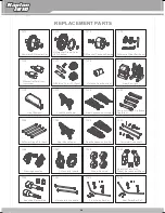
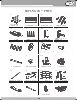
Page 28: ...es front rear Diff Pinion Gear 13T 2pcs Outdrive Gear Box front Gear Box 1pcs Front Bumper Front Shock Tower Front Suspension Arm Set Susp Arm Hinge Pin Brace front rear 3x30mm Hinge Pin 4pcs Rear Shock Tower Rear Suspension Arm Set Universal Drive shaft Steering Knuckles C Hubs with Inserts Wheel Hex Nuts Rear Hub Car Hex Wheel Ad each with 2pcs Rear Hub Carrier Axle Horizontal drive shafts Front...

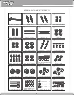
Page 29: ...ver Post Slipper Clutch complete with Main Gear Asbestos paper friction plate Reduction Gear Adjusting spring Adjusting spring mount Asbestos briquetting Dogbone Outdrive Slipper Clutch Reduction gear shaft Gear Connecting cups Aluminium Motor Mount 21T Motor Gear Aluminium Center Driveshaft Battery Tray and Posts Steering Rods Servo Saver Steering Arms Steering Connecting Plate Steering Servo Tur...

Page 30: ...ar Shock Spring black Front Shock Rods Rear Shock Rods Shock cap Shock seal cover Shock adjustmentring Shock absorber piston group Shock Sealing Set 4pcs Shock End Set Upper Lower Shock spring lower seat Front Rear shock absorber cylinder block Server crankset Front Tire Rim Set Front Tire Rim Set Tyre Inserts front 2pcs Tyre Inserts rear 2pcs Antenna tube antenna cap Asbestos paper friction plate...

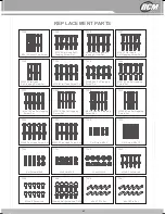
Page 31: ...M3X20 Flat Head Self tapping Screw Set M3X8 Flat Head Screw Set M3X6 Pan Self tapping Screw Set M3X10 Pan Self tapping Screw Set M3X12 Pan Self tapping Screw Set M3X14 Pan Self tapping Screw Set M3X16 Pan Self tapping Screw Set M3X20 Pan Self tapping Screw Set M3X8 Pan Head Screw Set M3X10 Pan Head Screw Set Set Screw M3x3 Set Screw M3x10 Set Screw M4x4 Lock Nut M2 5 Lock Nut M4 M3x4 1 Screw rod M...

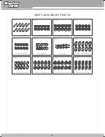
Page 32: ...x11 Pin Set Ball bearing φ8x5x2 5 Ball bearing φ10x5x4 Ball bearing φ15x10x4 E button φ2 5x0 4 Ball Head Set R Pin Set φ8xφ5 1x0 3 Washers φ10xφ5 5x0 3 Washers φ8xφ3 2x0 5 Washers Rear Wheel Shaft Washers Differential sealring Body white 7239 Body yellow 7240 Body transparent 7241 Tail Wing White yellow black Body and tail sticker Dust cover B 10E 34 32 ...

Page 33: ...0 3 5KG Servo Brushless ESC 60A Li Po 3200mAh 7 4V 18C Brushless Motor Kv3600 35 7284 7286 7288 7289 7283 7285 7287 R E P L A C E ME NT P A R T S Brushed ESC Ni MH 3000mAh 7 2V 15C Brushed Motor 540 Servo 6 15kgs Brushless ESC 45A 120A LiPo 3600 6000mAh 7 4v 11 1v Motor Brushless 4 Poles 3000 3900kv 35 33 ...

Page 34: ...Por medio de la presente RC MITICO S L declara que el equipo de radiocontrol cumple los requisitos esenciales y cualesquiera otras disposiciones aplicables o exigibles de la Directiva 1999 5 CE Hereby RC MITICO S L declares that this Radio Control Equipment is in compliance with the essential requirements and other relevant provisions of Directive 1995 5 EC IMPORTADOR CIF B 86452125 28914 Leganés ...

Reviews: