background image


Installation Guide | Issue 2.0 | The Eden Power Tray


Page 1


The ETL Symbol is a UK registered certification mark of the 

Department of Energy and Climate Change 

Authorised User: 03195 

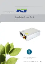
Installation & User Guide


Eden Power Tray


Summary of Contents for Eden Compact series

Page 1: ...tion Guide Issue 2 0 The Eden Power Tray Page 1 The ETL Symbol is a UK registered certification mark of the Department of Energy and Climate Change Authorised User 03195 Installation User Guide Eden Power Tray ...

Page 2: ...111 Minor Assisted Defrost Tray Connectivity 15 2 10 EP3111 Minor Assisted Defrost Tray Circuit Diagram 16 2 11 EP3110 3112 Off Cycle Defrost Tray Connectivity 17 2 12 EP3110 3112 Off Cycle Defrost Tray Circuit Diagram 18 2 13 All Variants Sensor Communication Network Connections 19 2 14 All Variants Tray End View 20 3 SETTING THE CONTROLLER UP 21 3 1 Front panel display keys icons 21 3 2 Using th...

Page 3: ...CT DETAILS 47 9 APPENDICES 48 9 1 Cycle Time function Times menu Ti13 48 9 2 Defrost Cycle Fans Off 49 9 3 Defrost Cycle Fans On 50 9 4 Integral Compressor Action 51 9 5 Remote Display 52 9 5 1 Panel Cut out 52 9 5 2 Remote Display 53 9 5 3 Retaining Clips 53 9 5 4 Remote Display Module 53 10 EUROPEAN DECLARATION OF CONFORMITY 54 ...

Page 4: ...et control panels to safeguard easy replacement of legacy units The assisted defrost variants also provide an external connection for defrost heater klixons to provide further safety features The Eden Compact controller incorporated into each of the power tray variants was designed as the first all in one compact refrigeration controller requiring no additional communication modules The Eden Compa...

Page 5: ...P3126 30A Assisted defrost LSV RS485 EP3113 30A Assisted defrost EEV RS485 EP3114 30A Assisted defrost LSV IP EP3123 30A Assisted defrost EEV IP EP3124 External Defrost contactor LSV RS485 EP3117 External Defrost contactor EEV RS485 EP3118 External Defrost contactor LSV IP EP3127 External Defrost contactor EEV IP EP3128 Hot Gas defrost LSV RS485 EP3119 Hot Gas defrost EEV RS485 EP31110 Hot Gas def...

Page 6: ... Contactor EP3118 EEV KTUC09 Tray External Contactor EP3111 LSV Only Minor Assisted Defrost EP3110 LSV Off Cycle Defrost ALL VARIANTS EP3112 EEV Off Cycle Defrost ALL VARIANTS 1 1 3 Power Tray Mating Connectors Eden Power Tray Mating Connectors Incoming Mains Supply Connector mates with Weidmuller STVS3 161699 RCS Part Code KS3STVS00 Cable Clamp Strain Relief for above connector Weidmuller STVS3ZE...

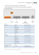
Page 7: ...utral 4 LSV EEV Live 2A Internal MCB CB 8 5 LSV EEV Neutral 6 Fans Live 4A Internal MCB CB 9 7 Fans Neutral 8 Lights Live 6A Internal MCB CB 5 9 Lights Neutral 10 Earth STV2 Pin Number Function Rating Designation 1 Earth 2 Suction Live 2A Internal MCB CB7 3 Suction Neutral 4 Not Used 5 Not Used 6 Not Used 7 Not Used 8 Trim Heater Live 10A Internal MCB CB 6 9 Trim Heater Neutral 10 Earth Defrost Sa...

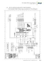
Page 8: ...lation Guide Issue 2 0 The Eden Power Tray Page 8 10A Assisted Defrost Circuit Diagram The Eden Power Tray 2 2 EP3115 EP3125 LSV EP3116 EP3126 EEV 10A Assisted Defrost Major Legacy replacement Circuit Diagram ...

Page 9: ...B CB 8 5 LSV EEV Neutral 6 Fans Live 4A Internal MCB CB 9 7 Fans Neutral 8 Lights Live 6A Internal MCB CB 5 9 Lights Neutral 10 Earth STV2 Pin Number Function Rating Designation 1 Earth 2 Suction Live 2A Internal MCB CB 7 3 Suction Neutral 4 Defrost Live 10A Internal MCB CB 3 5 Defrost Neutral 6 Defrost Live 10A Internal MCB CB 4 7 Defrost Neutral 8 Trim Heater Live 10A Internal MCB CB 6 9 Trim He...

Page 10: ...de Issue 2 0 The Eden Power Tray Page 10 30A Assisted Defrost Circuit Diagram The Eden Power Tray 2 4 EP3113 EP3123 LSV EP3114 EP3124 EEV 30A Assisted Defrost KTUC09 Electric Defrost Legacy replacement Circuit Diagram ...

Page 11: ... LSV EEV Neutral 6 Fans Live 4A Internal MCB CB 9 7 Fans Neutral 8 Lights Live 6A Internal MCB CB 5 9 Lights Neutral 10 Earth STV2 Pin Number Function Rating Designation 1 Earth 2 Suction Live 2A Internal MCB CB 7 3 Suction Neutral 4 Hot Gas S V Live 2A Internal MCB CB 3 5 Hot Gas S V Neutral 6 Not Used 7 Not Used 8 Trim Heater Live 10A Internal MCB CB 6 9 Trim Heater Neutral 10 Earth Defrost Safe...

Page 12: ...n Guide Issue 2 0 The Eden Power Tray Page 12 Hot Gas Defrost Circuit Diagram The Eden Power Tray 2 6 EP3119 EP3129 LSV EP31110 EP31210 EEV Hot Gas Defrost KTUC09 Hot Gas Defrost Legacy replacement Circuit Diagram ...

Page 13: ...eutral 6 Fans Live 4A Internal MCB CB 9 7 Fans Neutral 8 Lights Live 6A Internal MCB CB 5 9 Lights Neutral 10 Earth STV2 Pin Number Function Rating Designation 1 Earth 2 Suction Live 2A Internal MCB CB 7 3 Suction Neutral 4 External Defrost Contactor Live 2A Internal MCB CB 3 5 External Defrost Contactor Neutral 6 Not Used 7 Not Used 8 Trim Heater Live 10A Internal MCB CB 6 9 Trim Heater Neutral 1...

Page 14: ...de Issue 2 0 The Eden Power Tray Page 14 External Defrost Contactor Circuit Diagram The Eden Power Tray 2 8 EP3117 EP3127 LSV EP3118 EP3128 EEV External Defrost Contactor KTUC09 Tray Legacy replacement Circuit Diagram ...

Page 15: ...gnation 1 Earth 2 Defrost Live 16A Internal MCB CB4 3 Defrost Neutral 4 LSV EEV Live 2A Internal MCB CB 6 5 LSV EEV Neutral 6 Fans Live 2A Internal MCB CB 5 7 Fans Neutral 8 Lights Live 6A Internal MCB CB 3 9 Lights Neutral 10 Earth Trim Heater STV Pin Number Function Rating Designation 1 Trim heater Live 6A Internal MCB CB 2 2 Trim Heater Earth 3 Trim Heater Neutral Eden controller power is suppl...

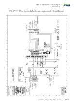
Page 16: ...Installation Guide Issue 2 0 The Eden Power Tray Page 16 Minor Assisted Defrost Circuit Diagram The Eden Power Tray 2 10 EP3111 Minor Assisted Defrost Legacy replacement Circuit Diagram ...

Page 17: ...Defrost Connectivity Details STV1 Pin Number Function Rating Designation 1 Earth 2 Curtain Fan Live 4A Internal MCB CB 3 3 Curtain Fan Neutral 4 LSV EEV Live 2A Internal MCB CB 5 5 LSV EEV Neutral 6 Fans Live 4A Internal MCB CB 4 7 Fans Neutral 8 Lights Live 6A Internal MCB CB 2 9 Lights Neutral 10 Earth Eden controller power is supplied via an internal 2A MCB CB 1 ...

Page 18: ...Installation Guide Issue 2 0 The Eden Power Tray Page 18 Off Cycle Defrost Circuit Diagram The Eden Power Tray 2 12 EP311 EP3120 LSV EP3112 EP3122 EEV Off Cycle Defrost Circuit Diagram ...

Page 19: ... Off Sensor Signal 4 Air Off Sensor Ground 5 Evaporator In Sensor Signal Optional Set up option see section 3 2 1 SU11 6 Evaporator in Sensor Ground 7 Evaporator Out Sensor Signal Optional Set up option see section 3 2 1 SU11 8 Evaporator Out Sensor Ground 9 Defrost Termination Sensor Signal Optional Set up option see section 3 2 4 DF8 10 Defrost Termination Sensor Ground 11 RS485 Communication Ne...

Page 20: ...Installation Guide Issue 2 0 The Eden Power Tray Page 20 Chassis End View The Eden Power Tray 2 14 All Variants End View ...

Page 21: ...f the user wishes to confirm modify parameters using the RCS system manager then the Eden controllers will need to be logged onto the system to achieve this please complete the Setup and Address sections as identified on pages 8 11 before proceeding to use the system manager Controllers can be pre commissioned with identical non default parameter sets via the use of a PC connected directly into th...

Page 22: ...enu Page 10 Service See Parameter Ti9 Page 18 HACCP See Parameter Su9 Page 9 Valve Illuminated when Relay 1 is on Pages 28 29 Fans Illuminated when Relay 2 is on Pages 28 29 Lights Illuminated when Relay 3 is on Pages 28 29 Defrost Illuminated when Relay 5 is on Pages 28 29 Network Off No Network attached network failure On Network Established ...

Page 23: ...pressing the enter key again will allow access to that group as described above The following pages provide details of each menu group in order It is recommended that the user follows this sequence to ensure correct setup is achieved If no buttons are pressed for a period greater than 3 minutes the display will revert to indicating the actual cabinet temperature This applies to all menus Display T...

Page 24: ... previous menu without saving I D Parameter Range Units Deflt LSV Deflt EEV Information Su1 Unit Type 0 HT Integral 1 LT Integral 2 HT Remote Case 3 LT Remote Case 4 HT Coldstore 5 LT Coldstore 4 4 Options 1 and 2 not valid if EEV variant Su2 Control Probe Type 0 Use Air On Probe 1 Use Log Probe Air On Air On Selects between using the air on or the log probe as the control temperature If Su3 is se...

Page 25: ... Case Clean Default for cabinet type 3 and 4 is case clean If unit type 1 or 2 selected su1 then default value becomes 2 C2 Fault If unit type 5 or 6 selected su1 then default becomes 1 Man Trapped alarm All digital inputs are contact sense N O N C for alarm Su9 HACCP Function 0 Off 1 On 2 Flashing 0 Off 0 Off Selects the state of the front panel HACCP icon Su10 Sensor Type 0 PT1000 1 5K NTC 2 10K...

Page 26: ...t LSV Deflt EEV Information 485A Controller RS485 communication address unit number 0 0 499 9 0 0 0 0 Allows the user to set the controllers network address for RS485 legacy systems 485C Controller RS485 communication baud rate 0 9600 1 600 9600 9600 Allows the user to set the controllers network baud rate for RS485 legacy systems IP 1 IP Address Byte 1 0 255 0 0 Allows the user to set the first b...

Page 27: ...ess Gt3 Network Gateway Address Byte 2 0 255 0 0 Allows the user to set the third byte of the network gateway address Gt4 Network Gateway Address Byte 2 0 255 0 0 Allows the user to set the fourth byte of the network gateway address NtP1 NTP server Address Byte 1 0 255 0 0 Allows the user to set the first byte of the NTP server address NtP2 NTP server Address Byte 2 0 255 0 0 Allows the user to se...

Page 28: ...he previous menu without saving I D Parameter Range Units Deflt LSV Deflt EEV Information rF1 Force Refrigeration No Yes No No Allows the user to force the controller into a forced refrigeration state During the force refrigeration state any scheduled defrosts will be ignored The controller will remain in this state until either NO is selected or a period of 60 minutes has elapsed rF2 Temperature ...

Page 29: ... 5 0 HT 35 0 LT 5 0 HT 35 0 LT Sets the log probe under temperature alarm setpoint NOTE N A will be displayed if Su3 is not set to 2 rF12 EEV Minimum Opening 0 100 15 15 Sets the minimum valve opening during normal operation The controller will prevent the valve from closing below this value N A will be displayed if LSV version rF13 Manual EEV Control 0 No 1 Yes 0 No 0 No Allows the user to manual...

Page 30: ...FUNCTION key to return to the previous menu without saving I D Parameter Range Units Deflt LSV Deflt EEV Information dF1 First Defrost Time 00 01 23 59 hh mm 01 00 01 00 Sets the first scheduled defrost time dF2 Number of Defrosts per Day 0 8 6 6 Sets the number of defrost cycles per day Automatically spaced equally from the first defrost time dF1 dF3 Maximum Defrost Duration 00 00 01 59 hh mm 00 ...

Page 31: ...ng used dF10 Suction Valve after Hot Gas defrost Open Closed Closed Closed Allows the user to select if the suction valve is open or closed during the drain down period Only applicable if Hot Gas defrost is selected at dF9 dF11 Force Defrost Yes No No No Sets the controller into defrost The controller will remain in this mode until either No is selected or max defrost duration Df3 time is exceeded...

Page 32: ...eflt LSV Deflt EEV Information Fn1 Fans Only Mode 0 No 1 Yes 2 Lights and Fans Only 0 No 0 No Allows the user to set the controller into Fans Only Mode The controller will remain in this mode until No is selected Fn2 Maximum Fans off Time 0 60 mm 0 0 Maximum time for which the fans are switched off following draindown Fn3 Fans Off Temperature During Defrost 40 0 C 35 0 C C 8 0 C HT 10 0 C LT 8 0 C...

Page 33: ...on sensor temperature or Air On temperature which when achieved will allow fans to be switched on Note N A will be displayed if not type 4 or 5 coldstore Fn8 Fans Pulse Time 5 600 ss 60 60 Time in seconds for which the fans will alternate between on and off if Fn6 is set to yes Fn9 Door Open State Closes Valve 0 No 1 Yes 0 No 0 No Allows the user to select if a door open state closes the evaporato...

Page 34: ... Allows the user to set the correct time of day into the controller Note on networked systems the time of day will automatically be down loaded from the host system ti2 Current Date 01 01 31 12 dd mm 00 00 00 00 Sets the controllers current date ti3 Current Year 2012 2100 0000 0000 Sets the controllers current year ti4 Time of Next Defrost hh mm Allows the user to view the time of the next schedul...

Page 35: ... door has been continuously open for Note N A will be displayed if not type 4 or 5 coldstore ti17 Door Interlock Time 0 60 mm 0 HT 5 LT 0 HT 5 LT Maximum time for which fans and or inlet valve are off closed when a cold store door is open Note N A will be displayed if not type 4 or 5 coldstore ti18 Compressor s start holdoff Time 0 15 mm 4 4 Time period following initial power up of the controller...

Page 36: ...ature C Displays the current Air On sensor Temperature St2 Air Off Temperature C Displays the current Air Off sensor Temperature St3 Evaporator In Temperature C Displays the current Evap In sensor Temperature St4 Evaporator Out Temperature C Displays the current Evap Out sensor Temperature St5 Superheat C Displays the current superheat Temperature St6 Defrost sensor Temperature C Displays the curr...

Page 37: ...St14 EEV percentage open Displays the current percentage opening of the EEV N A will be displayed if LSV version St15 Compressor 1 Fault Yes No Displays the current fault status of C1 Integral only St16 Compressor 2 Fault Yes No Displays the current fault status of C2 Integral only St17 Compressor 1 Running Yes No Displays the current status of controllers C1 output Integral only St18 Compressor 2...

Page 38: ... menu I D Parameter Range Units Deflt LSV Deflt EEV Information AL1 Any Alarms Yes No Allows the user to quickly establish if any alarm conditions are currently Active AL2 Air On OT Yes No Indicates if the controller currently has an Air On over temperature alarm AL3 Air Off OT Yes No Indicates if the controller currently has an Air Off over temperature alarm AL4 Air On Sensor Failure Yes No Indic...

Page 39: ...roller currently has a Man Trapped alarm Note N A will be displayed if not type 4 or 5 coldstore AL12 Insufficient Data Yes No Indicates if the controller currently has an Insufficient Data alarm Note Usually occurs when defrost time 1 has not been set AL13 Compressor 1 Alarm Integral Only Yes No Indicates if the controller currently has a Compressor 1 Fault AL14 Compressor 2 Alarm Integral Only Y...

Page 40: ... via controller schedule see Li2 Li15 2 Always Off 3 Always On Li2 Sunday Lights On Time 00 00 23 59 hh mm 08 00 08 00 Available if Li1 set to 1 Local Li3 Sunday Lights Off Time 00 00 23 59 hh mm 22 00 22 00 Available if Li1 set to 1 Local Li4 Monday Lights On Time 00 00 23 59 hh mm 08 00 08 00 Available if Li1 set to 1 Local Li5 Monday Lights Off Time 00 00 23 59 hh mm 22 00 22 00 Available if Li...

Page 41: ...ew and modify that particular value by using the UP DOWN keys to either increment or decrement the default value Once the desired value is displayed press ENTER again to save or use the FUNCTION key to return to previous menu without saving Note Caution should be used when setting this value as the controller will remain in sleep mode indefinitely once selected I D Parameter Range Units Deflt LSV ...

Page 42: ...EST menu See table below Pressing ENTER whilst displaying SF1 will allow the user to view and modify the default value of NO to YES If YES is selected the controller will remain in self test for a period of two minutes or until NO is selected if sooner The FUNCTION key can be used to return to the previous menu I D Parameter Range Units Deflt LSV Deflt EEV Information SF1 Self Test No Yes No No Al...

Page 43: ...age 43 Cleaning The Eden Power Tray 4 Cleaning Only use a soft lint free cloth Abrasive cloths towels paper towels and similar items may damage the Eden controller Keep any liquids away from the controller don t use aerosol sprays solvents or abrasives ...

Page 44: ...20 0C to 65 0C Environmental Indoor use at altitudes up to 2000m IP30 Installation Category II Voltage fluctuations not to exceed 10 of nominal voltage 5 2 Dimensions Size 360mm W x 85mm H x 210mm D Approx Weight 3 80 K Grams without free end connectors Safety EN60730 1 EMC EN 55014 1 2006 A2 Ventilation There is no requirement for forced cooling ventilation Class 2 Insulation This unit MUST be Ea...

Page 45: ...45 Revision History The Eden Power Tray 6 Revision History Revision Date Author Amendments Comments 1 06 08 14 SRL First Draft Issued for internal review 2 06 02 15 SRL Various Amendments Circuit Diagrams updated Part Codes Updated General Text Corrections ...

Page 46: ...cification improvements the information contained within this document is subject to change at any time without prior notice RCS Energy Management shall not be liable for any errors or omissions for incidental or consequential damages either directly or indirectly resulting from the misuse of this product or associated document ...

Page 47: ...tact Details The Eden Power Tray 8 Contact Details RCS Energy Management Limited RMS House Kennet Side Newbury Berkshire RG14 5PX UNITED KINGDOM Tel 44 0 1635 231600 Fax 44 0 1635 231699 Email sales rcsenergymanagement co uk Website www rcsenergymanagement co uk ...

Page 48: ...e cycle time function will close the liquid solenoid valve if the valve has been open for greater than the cycle time parameter Ti13 and has been constantly within the dead band for this period The diagram below Fig 1 shows the cycle timer operation overlaid over the standard control loop The cycle time function can be disabled by setting Ti13 value to zero Fig 1 The benefits of using the cycle ti...

Page 49: ...Installation Guide Issue 2 0 The Eden Power Tray Page 49 Appendices The Eden Power Tray Appendix 2 9 2 Defrost Cycle Fans Off ...

Page 50: ...Installation Guide Issue 2 0 The Eden Power Tray Page 50 Appendices The Eden Power Tray Appendix 3 9 3 Defrost Cycle Fans On ...

Page 51: ...Installation Guide Issue 2 0 The Eden Power Tray Page 51 Appendices The Eden Power Tray Appendix 4 9 4 Integral Compressor Action ...

Page 52: ...Display The Eden Power Tray range is available in configurations to support remote display requirements The Eden Compact remote display unit maintains exactly the same fascia dimensions as the compact controller 9 5 1 Panel Cut out Please allow 35mm behind panel for display module and cable clearance 71mm 29mm ...

Page 53: ... end of the enclosure These have been designed to allow the fitment of the module through a panel cut out from the front 9 5 3 Retaining Clips The remote display unit maintains exactly the same functionality as the integral display variant of the Eden Compact with menu access parameter management and setup the same as previously described within this document 9 5 4 Remote Display Module Front view...

Page 54: ... requirements for household appliances electric tools and similar apparatus Immunity Hereby declare that Equipment Eden Power Tray Model Number s EP3110 EP3111 EP3112 EP3113 EP3114 EP3115 EP3116 EP3119 EP31110 Is in conformity with the applicable requirements of the afore mentioned standards directives The Technical construction file is maintained at RMS House Kennet Side Bone Lane Newbury Berkshi...

Reviews: