background image

RDC6334G Laser cutting system hardware user manual

SHENZHEN RUIDA TECHNOLOGY

15

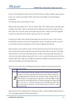
At the column of Origin Point setting, red box on the left of the option means forbidden, green box means
enable, you can click to switch back and forth. Parameters are saved before closing the dialog box
automatically
The remaining operations are the same as above.

Multiple origin points enable: “Yes” or “No” are optional. When “No” is selected, system uses single origin
point logic, press “Origin” button on the keyboard to set origin point and only this set origin point takes
effect. When “Yes” is selected, system uses multiple origin points logic, “Origin” button on the keyboard
invalid. User need to set the value of each origin point in the menu, see below.

Set origin point 1/2/3/4: after enabling multiple origin points logic, place the cursor on "Set as anchor
point 1/2/3/4", and press the "OK" key on the keyboard at this time, the system will use the current X/Y
axis coordinate value as the coordinate value of the corresponding origin point 1/2/3/4.

Next origin point: 0 to 4 is optional, it shows the origin points that will be used in the next picture that is
ready to work. Origin point No.0 represents origin point set by “Origin” button on the panel in the single
origin point logic. 1 to 4 indicates origin point sequence number in the multiple origin points logic. The
next origin point can be modified to any point from 1 to 4, so as to control the starting position of the next
work (provided that the origin point is enabled), and cannot be modified to the No.0 origin point (if it is a
single origin point logic, always take No.0 origin point).

Origin point 1 to 4 enable: when multiple origin points logic is enabled, the four origin points can be
individually disabled and enabled.

Once multiple origin points logic is selected, if the next origin point sequence
number is 1, and four origin points are all enabled, when initiate memory files
(including keyboard and PC start), or PC uses direct output to activate task and
when the option “Use original point as origin point” is selected, different origin
points will be used for each job started. The alternating sequence of origin point
is 1->2->3->4->1->2... When PC uses direct output to activate task, select “Take
the current point as origin point”, then the system takes current point as origin
point all the time.

Original position: Set the original position of display screen here, and choose different original position to
mirror the displayed graphics in different X/Y directions.

Summary of Contents for RDC6334G

Page 1: ...n The content include of electric connections and operating steps Read the manual to operate the systems RuiDa Technology Co Ltd Addr 202 203 B Block Technology Building NO 1057 Nanhai Avenue Nanshan...

Page 2: ...it store in a retrieval system or adapt thispublication in any form or by any means without the prior written permissionof RuiDa except as allowed under applicable copyright laws We have identifiedwor...

Page 3: ...conformity assessment procedure and the manufacturer s declaration of conformity in accordance with the relevant EU directive ROHS This product has been certified by EU legislation Restriction of Haza...

Page 4: ...r the use is wrong which may lead to the injury of the personnel please do not operate the personnel and related personnel easily until ensure the correct operation method and use method is correct be...

Page 5: ...rtant After receiving the product please check whether the outer package is intact check whether the product is complete after unpacking and whether all parts are intact If any damage is found please...

Page 6: ...ce 4 2 2 Main interface 5 2 3 speed setting 6 2 4 Max Min power settings 7 2 5 Layer parameter setting 8 Chapter 3 Menu functions 10 3 1 System information 11 3 2 System Configuration 11 3 3 Functions...

Page 7: ...RDC6334G Laser cutting system hardware user manual SHENZHEN RUIDA TECHNOLOGY 1 Section 1 Brief introduction of HMI and keys function CONTENTS HMI Introduction of key function...

Page 8: ...Laser on off Track To track current processing file File memory document and U disk file management Speed Set the current processing speed value Max power Set the current maximum power value Min powe...

Page 9: ...RDC6334G Laser cutting system hardware user manual SHENZHEN RUIDA TECHNOLOGY 3 Esc To stop working and cancel file preview when suspend working Enter To set layer parameter...

Page 10: ...cutting system hardware user manual SHENZHEN RUIDA TECHNOLOGY 4 Section 2 Main interface and functions introduction CONTENTS Boot interface Main interface Speed setting Max Min power settings Layer pa...

Page 11: ...1 Boot interface Boot screen will display when system is resetting as shown below Figure 2 1 Boot screen Boot screen could be modified by users by importing defined picture via PC software and then do...

Page 12: ...e current working status of the system which are system idle system pause system completed system running Network connection status To display the network status of the mainboard When the network comm...

Page 13: ...ion interface In the state of system idle users can perform file processing parameter setting file preview and other operations 2 3 Speed setting Press Speed button in the main interface a dialog box...

Page 14: ...s to enter a new value press Enter to confirm the input Press Esc to cancel the input and return to the previous interface press Del to delete the current value 2 4 Max Min power setting Press Max pow...

Page 15: ...lick layer parameter list with your finger or mouse to select a layer If there are multiple layers you can press and hold the middle of the list and drag down with your finger At this time the layer l...

Page 16: ...uccessful then press Enter to return main interface When modifying another layer parameter without closing the current layer setting window be sure to save the current layer parameter first if needed...

Page 17: ...Laser cutting system hardware user manual SHENZHEN RUIDA TECHNOLOGY 11 Section3 Menu functions CONTENTS System information System Configuration Functions Users parameter Vendor parameter Axis Reset S...

Page 18: ...of Menu a dialog box will pop up as following Figure 3 1 Click Read parameters button panel will read and display the information of motherboard Click Reset to clear Total Pieces Press the Esc button...

Page 19: ...ers button to save the modified parameters on the motherboard Press the Esc button to close dialog box and return back to previous interface Interface options are Ethernet and USB for selection Click...

Page 20: ...ameters after selecting Close the dialog box and return back to previous interface press Esc button to undo and return to System Configuration interface The types of display screen are 128X64 dot matr...

Page 21: ...Origin point No 0 represents origin point set by Origin button on the panel in the single origin point logic 1 to 4 indicates origin point sequence number in the multiple origin points logic The next...

Page 22: ...ters system will overwrite all current user parameters and manufacturer parameters with the default parameters set before 3 4 User parameters Click the User parameters button in the main interface of...

Page 23: ...of each parameter 3 5 Vendor Parameter Click the Vendor parameters button in the main interface of Menu a dialog box will pop up as following Pic 3 5 Operations are the same as above Please refer to t...

Page 24: ...RDC6334G Laser cutting system hardware user manual SHENZHEN RUIDA TECHNOLOGY 18 Figure 3 6 Operations are the same as above...

Page 25: ...RDC6334G Laser cutting system hardware user manual SHENZHEN RUIDA TECHNOLOGY 19 Section 4 File functions CONTENTS Memory files U disk files...

Page 26: ...file name and the number of processed pieces will be displayed on the list and the selected file will be previewed in the preview area on the right When there are multiple files click to select a file...

Page 27: ...interface all the current dialog boxes will be closed automatically and click Cancel button in the main interface to cancel preview operation Working hours preview display the total time of file proc...

Page 28: ...RDC6334G Laser cutting system hardware user manual SHENZHEN RUIDA TECHNOLOGY 22 Figure 4 1 3 The operations in this interface are the same as above...

Page 29: ...e 2 The operations in this interface are the same as above FAT32 and FAT16 file format of U disk are supported in this system Files must be placed in the root directory of the U disk to be recognized...

Page 30: ...RDC6334G Laser cutting system hardware user manual SHENZHEN RUIDA TECHNOLOGY 24 Section 5 Alarm information CONTENTS Alarm information...

Page 31: ...ormation will pop up during users operation or system operations e g water protection failure hard limit protection track out of bounds etc Here s an example The system has a water protection failure...

Page 32: ...RDC6334G Laser cutting system hardware user manual SHENZHEN RUIDA TECHNOLOGY 26 Section 6 Installation size CONTENTS Installation size...

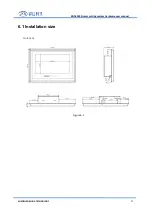
Page 33: ...RDC6334G Laser cutting system hardware user manual SHENZHEN RUIDA TECHNOLOGY 27 6 1 Installation size Unit mm Figure 6 1...

Page 34: ...any can not copy upload and send the manual without Ruida s permission Content will be revised or modified We will not send message to every users If there are any question or suggestion about our pro...

Reviews: