background image


User Guide 


Title 

Sub Title


Liftlog 1000 

Fork Lift Truck  

Weighing System 

Installation and Calibration 


Summary of Contents for Liftlog 1000

Page 1: ...1 User Guide Title Liftlog 1000 Fork Lift Truck Weighing System Installation and Calibration...

Page 2: ...information RDS Technology Ltd Cirencester Road Minchinhampton Stroud Glos GL6 9BH United Kingdom Ph 44 0 1453 733300 Fax 44 0 1453 733311 EMAIL info rdstec com Our policy is one of continuous improve...

Page 3: ...t wherever our products are used the various elements electrical or otherwise are disposed of responsibly at their end of life If you wish to discard our products then we advise that if unsure you con...

Page 4: ...lic Fitting Kits standard unless otherwise specified 9 1 6 Hydraulic Fitting Kits options 11 2 INSTALLATION 12 2 1 Drop Valve Pressure Sensor 12 2 1 1 Flow Rate Adjustment 14 2 2 Reference Sensor 15 2...

Page 5: ...Port Setup 27 3 3 4 Language Keyboard region 27 3 3 5 Instrument ID 27 3 3 6 Job No Ticket No 28 3 3 7 Save to USB 28 3 3 8 Load from USB 29 3 3 9 Overload Log 30 3 4 Factory Level Settings 31 3 4 1 A...

Page 6: ...vice and Support Department at the factory RDS Technology Ltd does not accept responsibility for faulty operation of the system or consequential damage as a result of poor workmanship of installation...

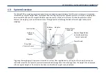
Page 7: ...eighing cycle can be started at any lift height while still allowing the load sufficient height to drop while weighing Triggering the weighing cycle operates a solenoid on a custom flow regulated valv...

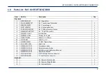
Page 8: ...M Mount Kit 1 7 S AC 411 1 005 Junction Box 1 8 S CB 410 1 026 Display Unit Cable 1 9 S CBL TIE 005 Cable Tie 370mm 5 10 S F724 003 Cable Tie 6 2 11 S FSNR 940221 BSP Dowty Seal 1 12 S HU 435 1 001 He...

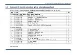
Page 9: ...1 3 S HY 500 9 101 3 8 BSPM 3 8 BSPM Adaptor 1 4 S HY 500 9 102 3 8 BSP Dowty Seal 1 5 S FSNR 940221 BSP Dowty Seal 1 K VHL INST 005 Tapped Port Kit ref section 1 6 for alternatives 1 Return to Tank...

Page 10: ...LIFTLOG 1000 INSTALLATION AND CALIBRATION 10 Fig 1 Hydraulic Components Lift Cylinder return line LP Tank Return 1 2 3 4 9 7 8 10 12 13 12 12 11 5 Fit as required for either P or T ports...

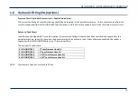
Page 11: ...return circuit Return to Tank Circuit In addition to the standard Hose kit supplied the correct tee fitting kit should have been specified and supplied for the particular machine to tee this hose into...

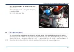
Page 12: ...The valve can be mounted in any orientation but leaving the flow adjustment screw accessible The drop valve pressure port marked P Pressure should be connected into the lift cylinder return line at a...

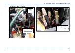
Page 13: ...LIFTLOG 1000 INSTALLATION AND CALIBRATION 13 Typical Drop Valve installation Tee lift cylinder return line to pressure port P Tee return port T to tank return line Drop valve...

Page 14: ...may need to be adjusted depending on the particular machine With the solenoid connected and the head unit powered up press the weigh button to energize the solenoid and observe the rate of drop Slacke...

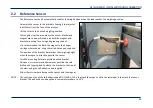
Page 15: ...It is recommended to attach the magnet to the hanger carriage where shown using theself adhesive pad supplied The position of the bracket determines the weighing height when the magnet is directly opp...

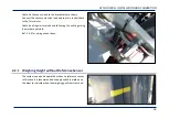
Page 16: ...o the Terminator Cable tie at regular intervals and following the existing wiring loom where possible Ref 2 4 4 for wiring connections 2 2 1 Weighing Height without Reference Sensor The system can als...

Page 17: ...head unit is dust tight and splash resistant however it is not rated for constant outdoor use For use in an outdoor environment it is recommended to mount the unit within a suitable secondary enclosur...

Page 18: ...the cables entering the end of the box to the PCB The Base Moulding can be mounted using the screws provided or can be left in line with the cables Connect the head unit lead onto the PCB header The r...

Page 19: ...work The head unit has reverse polarity protection and will not be damaged The LED on the Terminator PCB will not light if the 0V and V connections are reversed If the instrument does not power up whe...

Page 20: ...olour Terminator Connection Pressure Sensor on Drop valve Blue 10 P1 Brown 4 P1 V Drop Valve Solenoid Blue 16 DROP VALVE 0V Brown 6 DROP VALVE BROWN Reference Sensor Blue 13 0V Brown 20 REF SENSOR BRO...

Page 21: ...ress to freeze the real time graphical display for the pressure sensor and supply voltage NOTE If you wish you may take a snapshot of the screen or any other screen for that matter Insert a USB stick...

Page 22: ...e and Date Brightness Volume Calculator Nudge Diagnostics 2 5 Press and enter PIN default 4084 to access Technician Level Technician Home Screen Functions 3 3 1 Logging Options 3 3 2 Port Setup 3 3 3...

Page 23: ...main operating screen and then press to select the Setup menu To setup manually please refer to the following sections if required Factory Full Setup Wizard 3 2 Calibration 3 4 1 Sensor Setup 3 4 4 O...

Page 24: ...Select the functions that you wish to appear on the main operating screen 3 3 2 Logging Options Setup for logging output to any of the following Printer RDS ICP 300 printer or other printer Data CSV o...

Page 25: ...cation COM 2 Print Mode Short Load by Load Prints a summary of the last job cleared a Long Load by Load Prints a summary of the last job cleared space for customers Name and Address b Lift by Lift Pri...

Page 26: ...of data each time a job is cleared as csv string type R Load Record and adds it to a default file called TOTALS CSV e g R ID1 Job No Time Net Weight Tare Weight Store Name Reference Lift by Lift Auto...

Page 27: ...e language regional keyboard option from the list If the required language is not pre installed HEX files for alternative languages including the appropriate keyboard option may be available and can b...

Page 28: ...to a HEX file This allows you to clone another head unit with an identical setup The default file name is AL10ALL HEX Press and rename the file if desired Press Ent on the screen keyboard to download...

Page 29: ...g and Calib Loading ALL Settings All settings are contained in a HEX file with the default name AL10ALL HEX It is either a file with the factory default settings or is a file that has been saved from...

Page 30: ...ly installed instruments Select the appropriate HEX file from the list displayed and press to upload Text Load the Store descriptions Store references for all Stores and the Instrument ID text This fi...

Page 31: ...oint is calculated and displayed as a of maximum pressure 3 Enter the known weight of the calibration load This should ideally be near the maximum weight capacity in order to calculate the most accura...

Page 32: ...tor by 1 and vice versa However if enabled via the Sensor Setup screen it is recommended to use the Nudge function instead ref Operation manual 3 4 3 Linear Compensation Factors Normally there is a li...

Page 33: ...weigh button and the Sample Start Delay during which the weight is sampled and averaged Sample Start Delay The time after pressing the weigh button before the solenoid activates and weight sampling c...

Page 34: ...ad function may be disabled if desired in which case the load bar will not be displayed on the main operating screen Max Capacity The weight at which overload occurs Either i Select Max Capacity and t...

Page 35: ...u PIN and the Factory menu PIN NOTE If the Secure 0 Key setting is enabled via Sensor Setup then the Factory menu PIN is also that entered to access the Set Zero routine on the main operating screen 3...

Page 36: ...LIFTLOG 1000 INSTALLATION AND CALIBRATION 36 Issue Ref Date Description 1 0 4 8 15 Original issue 1 1 29 9 15 Ref CRQ 6658...

Reviews: