background image

37

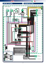
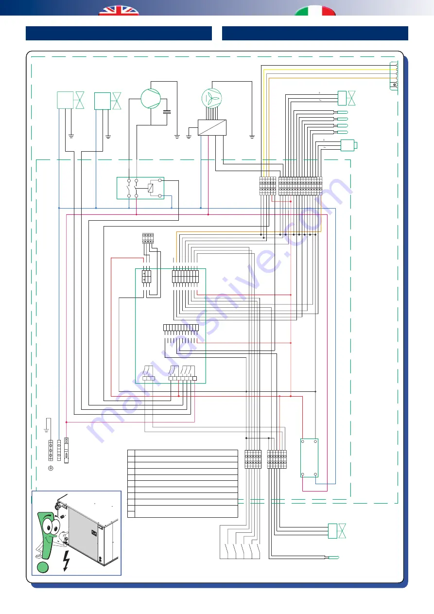
WIRING DIAGRAM

SCHEMI ELETTRICI

DA 1001 - Rev 00

1
2
3

4
5

+12V

5VS

1 3 5 7

GND AO

1

DI1

AO

2

DI2

AO

3

DI3

AI1 AI2 AI3 AI4 AI5 AI6 DI4 DI5 CO

M

A/+

CAN+

V      -

B/-

CAN-

V      +

9 11 13 15 17

2 4 6 8 10 12 14 16 18

1 3 5

2 4 6

NO6 NO7

CO
6/7

NO1 NO2

CO
1/2

NO3 NO4

 CO

3/4/5

NO5

EVCO

EPU3LXP

DO1..7

1 2 3 4

0

5

6

9 10

0

ALIM.

+

-

L

N

Output 24V DC

Input 240V AC

R

S

C

C

COMPRESSORE

COMPRESSOR

VENTILATORE

IMMISSIONE

INPUT

FAN

ELETTROVALVOLA 

DI CARICO 

CIRCUITO FRIGO

CHARGE ELECTRIC VALVE

DISCHARGE ELECTRIC VALVE

BL

UE

-BL

U

EVS

ELETTROVALVOLA 

DI SCARICO 

CIRCUITO FRIGO

EVC

BL

UE

-BL

U

VIOLET

-V

IOLA

PINK

-ROS

A

PRESSURE TRANSDUCER

TRASDUTTORE DI PRESSIONE

EVAPORATOR PROBE TEMPERATURE

OVERHEATING PROBE TEMPERATURE

PROBE WATER PRETREATMENT TEMPERATURE

PROBE INLET FAN TEMPERATURE

SONDA TEMP. EVAPORATORE

SONDA TEMP. SURRISCALDAMENTO

SONDA TEMP. ACQUA PRETRATTAMENTO

SONDA TEMP. VENTILATORE MANDATA

M

ATTUATORE MODULANTE

VALVOLA ACQUA CONDENSAZIOINE

CONDENSATION WATER 

VALVE MODULATING ACTUATOR

[+    ] 

RED

-ROSSO

[Y in] 

GREY

-GRIGIO

[-    ] 

BLACK

-NERO

BLACK

-NERO

YELLOW

-GIALLO

GREY

-GRIGIO

Q.E.

+ A B -

Not Used  - 

Non Utilizzato

[+    ]  

RED

-ROSSO

[Y out] 

WHITE

-BIANCO

[-    ]  

BLACK

-NERO

SONDA TEMP. CANALE DI MANDATA

CONSENSI

CONSENTS

0 11 12

18

0

0

19 0

0

16

0

17

22

13

0

0

24

23

N

L

N

L

N

L

0V

10V

REGOLATORE

ELETTRONICO

ELECTRONIC

REGULATOR

ORANGE

-ARANCIONE

SIGN. 0-10V INLET FAN REC.

-SIGN. 0-10V VENT. MANDATA REC.

GND

-GND

SIGN. 0-10V EXPULSION FAN REC.

-SIGN. 0-10V VENT. ESPULSIONE REC.

9 8 7 6

AI9

AO

6

DI6 DI7 DI8 DI9 CO

M

5 4 3 2 1

12 11 10

GND AI7 AI8

0 7 8

M

[+]
[Y in]
[-]

ATTUATORE MODULANTE

VALVOLA ACQUA PRETRATTAMENTO

DUCT INLET PROBE TEMPERATURE

PRETREATMENT WATER 

VALVE MODULATING ACTUATOR

AO

5

AO

4

14 15

20

21

RENEWAL CONTROL REC. +24V DC

-COMANDO RINNOVO REC. +24V DC

L

Kc

A2

A1

14

11

24

21

N

SUPPLY

-ALIMENTAZIONE

  230V 50Hz / 60Hz

(

NOT USED

)-(NON UTILIZZATO)

Neutro

Neutr

al

Fase

Phase

(

NOT USED

)-(NON UTILIZZATO)

DI3-

Dehumidification Consent  

- Consenso Deumidificazione

DI2-

Ventilation Consent 

- Consenso Ventilazione

DI1-

Season (Winter/Summer) 

- Stagione (Inverno / Estate)

DI5-

Renewal Consent  

- Consenso Rinnovo

GND-

Common DI/AI 

- Comune DI/AI / Massa aliment.

DI4-

Integration Consent 

- Consenso Integrazione

AI5-

Inlet Duct Ntc 

- Ntc canale mandata

0
1

2
3
4

5
6
7
8
9

10

AO2-

Pretreatment water valve actuator

- Attuat. valvola acqua pretrat.

+24VDC-

Valve actuator supply 

- Alimentaz. attuat. valvola

DO6-

N.A Clean contact alarm 

- Allarme  contatto pulito N.A

N

L

Summary of Contents for DA 1001

Page 1: ...rHandlingUnits UnitàTrattamento Aria DA 1001 TECHNICAL INSTALLATIONMANUAL MANUALETECNICO INSTALLAZIONE Dehumidifierhorizontalceilingmounted CommercialUnits Terziario Deumidificatore orizzontale a soffito ...

Page 2: ......

Page 3: ...o di Assistenza autorizzato dal Costruttore Alla fine dell installazione smaltire gli imballi secondo quanto previsto dalle normative in vigore nel Paese di utilizzo Esigere solo ricambi originali la mancata osservazione di questa norma fa decadere la garanzia SAFETY WARNINGS Readthismanualcarefullybeforeinstallingand orusingthe equipment and keep it in an accessible place This equipment constitut...

Page 4: ...rodotto da parte dell utente comporta l applicazione delle sanzioni previste dalla vigente normativa in materia The manufacturer declines all responsibility and considers the warranty invalid in the following cases Theaforementionedwarningsandsafetyregulations including those in force in the country of installation are not respected The information given in this manual is disregarded Thereisdamage...

Page 5: ...circuiti idronici 19 Testing Collaudo 21 Flow water setting Taratura portate acqua 21 Fan speed setting Taratura della velocità dei ventilatori 22 Summer functioning Funzionamento estivo 23 Winter functioning Funzionamento invernale 23 Distribution example Esempio di distribuzione 24 MAINTENANCE MANUTENZIONE 25 1 Ordinary maintenance 1 Manutenzione ordinaria 25 2 Extraordinary maintenance 2 Manute...

Page 6: ...iclaggio alle aziende preposte allo scopo e ridurne così l impatto ambientale The unit packaging must be removed with care ensuring that the machine is not damaged The materials which make up the packaging are different wood cardboard nylon etc Store them separately and deliver them for disposal or where appropriate recycling to the relevant companies thus reducing the environmental impact TESTING...

Page 7: ...ne integrazione potenza sensibile estiva e invernale acomando Iltelaiodellamacchina inlamierazincata contiene il gruppo di batterie alettate per il trattamento dell aria il circuito frigorifero per la deumidificazione il filtro dell aria per l aspirazione la vaschetta raccogli condensa il ventilatore di mandata ad alta efficienza e il quadro elettrico di comando e gestione L unitàèdotatadidisplayc...

Page 8: ...a 6 Condensing coil Batteria condensante 7 Evaporation thermostatic valve Valvola evaporante termostatica 8 Modulating hydraulic circuit condensation valve Valvola modulante circuito idraulico condensatore 9 Tank coil Batteria serbatoio 10 Tank fill valve Valvola di carico serbatorio 11 Tank drain valve Valvola di scarico serbatoio 12 Fan Ventilatore Circuits of the unit Circuiti machina DA 1001 1...

Page 9: ...uccessivi Icontrollidisicurezzavengonoeffettuatidallacentralinatramite i valori rilevati dalle sonde Sonda temperatura acqua pre trattamento Sonda temperatura evaporatore Sonda surriscaldamento Trasduttore di pressione Sonda temperatura vano ventilatore INTERNAL COMPONENTS DESCRIPTION COMPONENTS Components Component Description Compressor Rotative Pre treatment water sensor NTC sensor to detect th...

Page 10: ...alificato Durante tutte le procedure di installazione assicurarsi che l apparecchiatura non sia collegata alla rete elettrica L installazionedeveessereeffettuatasoloall interno degli edifici INSTALLATION INSTALLAZIONE 1 POSITIONING AND FIXING TO THE CEILING POSIZIONAMENTO E FISSAGGIO A SOFFITTO MAX 95 MAX 30 C OK min 5 cm m i n 4 0 c m Positioning indications Indicazioni di posizionamento Minimum ...

Page 11: ...11 mm ø8mm 2 476 811 1 Fixing to ceiling Fissaggio a soffitto min 40 cm min 20 cm min 60 cm X X Trap door Botola d ispezione 3 Washer Rondella Rubber mounts Gommino antivibrante ...

Page 12: ...am 3 4 F con detentore di regolazione portata C Condenser water outlet 1 2 F Uscita acqua condensatore 1 2 F D Condenser water inlet 1 2 F with flow rate adjustment lockshield valve Ingresso acqua condensatore 1 2 F con detentore di regolazione portata E ø20mmcondensationrubberdrain RDZkitcondensation drain Scarico in gomma ø20 mm per condensa kit scarico condensa RDZ E B C A A B C D D E 1 2 Scari...

Page 13: ...heck thatnotonlytheconnectionsbutalsothemachinehydraulic circuit are watertight as these could be damaged during transportation or on site during installation on this topic themanufacturerwillonlyberesponsibleforfactorydefects on the dehumidifier and under no circumstances accepts responsibility for indirect damage Thecondensationdrainandtheinletandoutletpipes must comply with the standards and la...

Page 14: ...nstalled in the pre treatment line only and should not interfere with the post treatment line WIRINGDIAGRAMFORCOMPLETEHYDRAULICCONNECTION SCHEMA DI COLLEGAMENTO IDRAULICO COMPLETO SCHEMA IDRAULICO CON VALVOLA MODULANTE HYDRAULIC DIAGRAM WITH MODULATING VALVE IN B OUT A IN D E OUT C Tank Accumulo Drain Scarico DA 1001 PRE COND AB A B Kv 2 7 KEY LEGENDA Circulation pump Circolatore Flow rate lockshi...

Page 15: ...onamento deve avvenire entro i valori sopra citati in caso contrario la garanzia viene a decadere immediatamente e ci sono rischi elettrici per le persone e il prodotto APERTURA SPORTELLO Thedehumidifiermustbeconnectedtoadisconnected earthedpowersocket Theelectricalsystemmustbeprotected against overloads short circuits and direct and indirect contactsandcomplywiththelawsandregulationsinforcein the...

Page 16: ...cable phase F neutral N earth The terminal of the tension line is provided with 16 A fuse if the unit does not start even though it is energized check this fuse CONSENSI DELL UNITÀ UNIT CONSENTS L N Consenso integrazione Integration consent 1 2 3 4 7 6 8 0 5 9 10 Stagione Estate Inverno Season Summer Winter Consenso deumidificazione Dehumidification consent Consenso ricircolo Recirculation consent...

Page 17: ...andoèattivaquestafunzionalitàdidefaultpartelamodalità ricircolo a meno che non venga chiuso il contatto rinnovo USCITA ALLARME Il relé di allarme è normalmente aperto in caso di anomalia il contatto si chiude E possibile rendere il contatto normalmente chiuso togliendo il ponticello denominato NC NO sul circuito stampato della scheda Information about the main electrical connections which must be ...

Page 18: ...ESSIONE MODBUS MODBUS CONNECTION A TX RX B TX RX B A e non utilizzati and not used serial card 1 A B serial card 1 WI SA Serie Design Unità 1 Unità 2 Unit 1 Unit 2 UNIT MODBUS ADDRESS INDIRIZZO MODBUS MACCHINA ...

Page 19: ...emperature inferiori ai 5 C per evitare il pericolo di ghiacciamento CARICAMENTO BATTERIA PRE TRATTAMENTO 1 Totaly open Totalmente aperto Max speed Velocità massima 2 3 Open until water flows Aperto finché non esce acqua FILLING OF THE HYDRONIC CIRCUITS Water filling in DA 1001 dehumidifiers is very important since the presence of air bubbles inside the finned coils and or in the plate exchanger c...

Page 20: ...F ON OFF ON OFF INTEGRATION INTEGRAZ 1 Totaly open Totalmente aperto Max speed Velocità massima 2 4 3 Open until water flows Aperto finché non esce acqua CARICAMENTO CONDENSATORE A PIASTRE CARICAMENTO PRE TRATTAMENTO CON VALVOLA MODULANTE WATER FILLING FOR PLATE CONDENSER WATER FILLING FOR PRE TREATMENT COIL WITH MODULATING VALVE ...

Page 21: ...umidity value this test is not valid with temperature values inferior to 26 C Check the temperature detected by the flow sensor Incaseof highhumidity 26 C65 RHor28 C60 RH theoutlet temperatureshouldbeabout17 C whileincaseoflowerhumidity the detected flow temperature should be approximately 16 C The test can be performed more accurately if SR 1001 unit is used and it works in fresh air ventilation ...

Page 22: ...re the required flow Low flow rate values will cause malfunctioning in the DA1001unit thusactivatingalarmsblockingtheunit with manual reset SET VENTILATORE IMMISSIONE IN RICIRCOLO Non scendere a portate inferiori a 800 mc h d aria in quantol unitàDA1001potrebbeattivareallarmiconblocco macchina a riarmo manuale Non salire a portate superiori a 1200 mc h d aria in quanto si creano problemi di scaric...

Page 23: ... Integrazione La Deumidificazione entra in funzione quando viene chiuso il contatto di deumidificazione vedere cap 3 Collegamenti elettrici L unità inizierà a deumidificare mantenendo una temperatura di uscita neutra rispetto a quella in ingresso La temperatura è impostata a 26 C ed è comunque modificabile da parametro vedere cap Centralina L Integrazioneentrainfunzionequandovienechiusoilcontatto ...

Page 24: ...24 ESEMPIO DI DISTRIBUZIONE DISTRIBUTION EXAMPLE ...

Page 25: ...pposite pannellature fissandole con le viti di serraggio All the extraordinary maintenance operations described in this chapter MUST ALWAYS BE CARRIED OUT BY QUALIFIED PERSONNEL Before performing any intervention on the unit or before accessing internal parts ensure that the electrical power supply has been disconnected There are moving components inside the unit Take particularcarewhenoperatingin...

Page 26: ... motor it is not necessary to remove the fan Per la sostituzione del conden satore elettrico del ventilatore si trova a fianco del motore non è necessario rimuovere il ventilatore OFF Spento Remove the two screws and bracket highlighted 4 holding the fan housing then lift slightly and remove it from the machine Rimuovere infine le due viti e la staffa evidenziata 4 che blocca no il corpo ventilato...

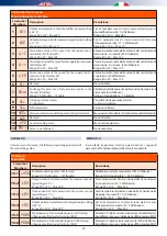
Page 27: ...scription Descrizione Indicates SUMMER season as active Indica la stagione ESTATE attiva Indicates WINTER season as active Indica la stagione INVERNO attiva Not used Non usato It means that the compressor operates if it flashes it means that the fan is going to start e g at the beginning or in case of defrosting Indica il compressore attivato se lampeggia è in attesa di attivarsi ad esempio all av...

Page 28: ...n Descrizione Exitmenus listofparametersandparametervalue without saving the value and go back to the previous level Si ottiene l uscita da menù da elenco parametri da valore parametro senza salvataggio valore e ritorno a livello precedente Not used Non utilizzato Scrolling the folders and parameters display upwards Parameter value increase if in parameter value modification mode Scorrimento verso...

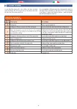
Page 29: ...re 10 H2Ov Menu parameters modulating valve H2 0 pretreatment MenuparametrivalvolaH2 0modulantepretrattamento 11 bvS Not used Non utilizzato 12 inFo General reading menu Menu letture generali 13 PAr1 Access is not allowed Non accessibile H2O MENU It can be set via this menu the following operating parameters of the modulating valve MENU H2O E possibile impostare tramite questo menu i seguenti para...

Page 30: ...rcentuale del voltaggio corrente della valvola modulante condensazione 12 7 H2Op Percentage value of the current voltage of the modulating pretreatment valve Valore in percentuale del voltaggio corrente della valvola modulante pretrattamento 12 8 Ueli Percentage value of the speed inlet fan Valore percentuale in utilizzo del set velocità ventilatore immissione 12 9 UEle Percentage value of the spe...

Page 31: ...ase the signal is continuous it is necessary to cut off the tension to the controller for resetting Intervento del pressostato di massima pressione refrigerante In tale caso la segnalazione è persistente per cui è necessario togliere l alimentazione al controllore per permettere il reset 3 Damage on the temperature sensor of the evaporator Guasto alla sonda di temperatura evaporatore 4 Alarm disch...

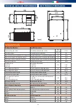
Page 32: ...y DA DA SR Prevalenza disponibile Solo DA DA SR Pa 390 301 Pre cooling water flow rate Portata acqua pre raffreddamento l h 1000 Pre cooling water outlets Attacchi acqua pre raffreddamento 3 4 F Condensation water flow rate Portata acqua condensazione l h 130 Condensation water outlets Attacchi acqua condensazione 1 2 F Pre cooling water head loss Only DA DA Modulating Valve Perdita di carico acqu...

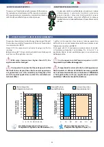
Page 33: ...il normale funzionamento né tantomeno l affidabilità e l integrità delle unità per applicazioni particolari contattare l ufficio tecnico del Costruttore Thegraphsshownbelowdescribetheoperatingrangeoftheunit The maximum permitted temperature of the water for operation in summer mode is 18 C Above 30 C the compressor is excluded leaving only the fan running Between30and55 Citispossibletoactivatethev...

Page 34: ...Resa in deumidificazione e integrazione in funzione della temperatura in ingresso all unità umidità relativa ON SUMMER Performance in dehumidification mode according to the temperature relative humidity and temperature of the chilled water DA SR 1001 Performance in dehumidification integration mode DA SR 1001 Resa in deumidificazione integrazione Inlet air Aria in ingresso Outlet air Aria in uscit...

Page 35: ...a acqua l h Head loss kPa Perdita di carico kPa Pretrattamento Pretrattamento valvola modulante INVERNALI Resa integrazione invernale massima in base alla differenza di temperatura tra aria in ingresso alla macchina e temperatura dell acqua ON WINTER Maximumsensibleheatingcapacityaccordingtothetemperature difference between inflow air into the unit and water PERDITA DI CARICO CIRCUITO IDRAULICO PR...

Page 36: ...procedere con l accoppiamento SR PRESSURES DROP Pressure drop value in SR units which should be subtracted from the aeraulic performance of the DA units in case of combination into UC units PREVALENZE UTILI ALLA BOCCHETTA DI IMMISSIONE AVAILABLE PRESSURES TO THE INTAKE OUTLET Air flow rate m3 h Portata aria m3 h Performance Pa Prevalenza utile Pa 0 100 200 300 400 500 500 1000 1500 2000 2500 3000 ...

Page 37: ...RED ROSSO Y out WHITE BIANCO BLACK NERO SONDATEMP CANALE DI MANDATA CONSENSI CONSENTS 0 11 12 18 0 0 19 0 0 16 0 17 22 13 0 0 24 23 N L N L N L 0V 10V REGOLATORE ELETTRONICO ELECTRONIC REGULATOR ORANGE ARANCIONE SIGN 0 10V INLET FAN REC SIGN 0 10VVENT MANDATA REC GND GND SIGN 0 10V EXPULSION FAN REC SIGN 0 10VVENT ESPULSIONE REC 9 8 7 6 AI9 AO6 DI6 DI7 DI8 DI9 COM 5 4 3 2 1 12 11 10 GND AI7 AI8 0 ...

Page 38: ...38 NOTES ANNOTAZIONI ...

Page 39: ......

Page 40: ...bit ly rdzwebsite 9100404 01 03 2017 ...

Reviews: