US FLOOR / FLOOR
Minichiller inverter Duo
16
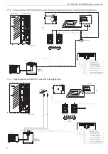
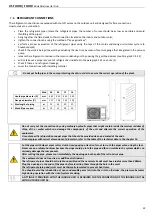
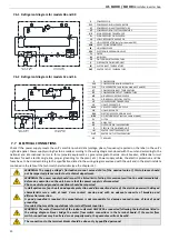
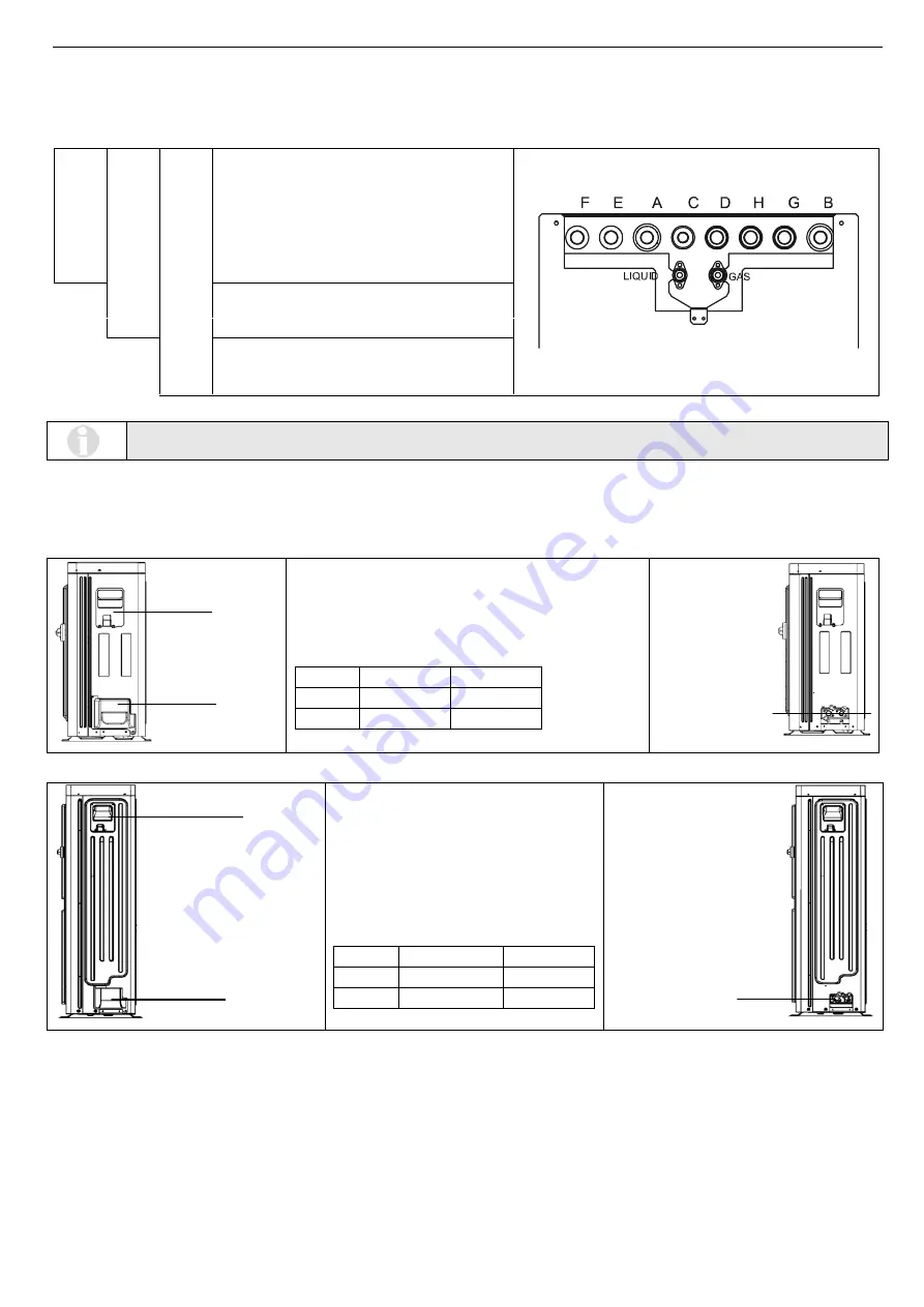
7.4.2 Connections positions
7.4.2.1
Indoor unit
A.
From the plant (1”M)
B.
To the plant (1”M)
C.
Water supply inlet (3/4”M)
D.
The user DHW-R (3/4”M)
I.
Liquid line (see Paragraph 15.3)
L.
Gas line (see Paragraph 15.3)
F.
To the solar plant (3/4”M)
E.
From the solar plant (3/4”M)
For DHW-R user, it means the point(s) of using of domestic hot water produced by the instantaneous preparer DHW.
The DHW-R means “rapid” production of the domestic hot water.
7.4.2.2
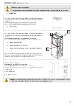
Outdoor unit
Units 06 and 09
A. Power supply cover (to reach the terminal block)
B. Gas connec
tion
s cover
C. Gas connec
tions
Models
Liquid pipe
Gas pipe
06
1/4 SAE
1/2 SAE
09
3/8 SAE
5/8 SAE
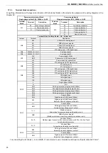
Units 12 and 16
A. To reach the power supply and signal
cables (remove the rear side cover to
reach the terminal block)
B. Gas connec
tion
s cover
C. Gas connec
tions
Models
Liquid pipe
Gas pipe
12
3/8 SAE
5/8 SAE
16
3/8 SAE
5/8 SAE
7.4.3 Drainage system connection
7.4.3.1 Indoor unit
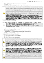
The connec
ti
on of a condensate drainage system is not necessary for the indoor units since all pipes and cold components are
insulated with closed-cell foam of an adequate thickness.
B
A
C
B
A
C
FLOOR
FLOO
R-S
FLOO
R / FLOO
R-S wi
th boile
r kit
I
L
G.
From the boiler (3/4”M) (optional)
H.
To the boiler (3/4”M) (optional)


