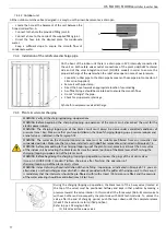
US FLOOR / FLOOR
Minichiller inverter Duo
20
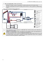
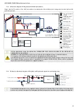
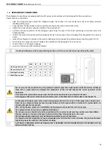
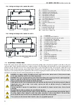
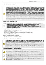
7.5.2 Schematic diagram of the plant with DHW recirculation
Please note that the
opti
on of the DHW r
ecirculati
on is available when the ad
ditio
nal plant management module (op
tional
GI2
op
tion
al) is present.
To
DH
W
-R
ut
ili
ty
Addi
ti
onal
expansion vessel
(not supplied)
Expansion
vessel
Fr
om
th
e
sol
ar
pl
an
t
THIS RECOMMENDED CONNECTIONS
SHOULD BE DONE BY THE INSTALLER
Hydronic circuit
Indoor unit
(model: FLOOR-S)
OUTDOOR UNIT
Piping connec
ti
on for
gas and liquid shall be
done by the installers
To
th
e
so
la
rp
la
nt
Solar plant
expansion vessel
(not supplied)
To the domes
ti
c utili es
Charging/topping up pipe
Water
supply
inlet
To the plant
DHW circula
ti
on
Boiler
To the boiler (technical water)
From the plant
PLANT
P
T
P
T
Key
Filter with extractable
cartridge
Loading group with
pressure reducer
device
Discharging valve
3 bar relief valve
Shut
-off
valve
Check valve
Manometer 0-6 bar
Dial thermometer
3-way an
ti-s
calding
thermosta
ti
c valve
Domestic water
mixer
NTC temp. sensor for
immersion (solar
collector)
DHW recircula
tion
temp. sensor
Circulator pump
All the components inside the dashed line "CONNECTIONS THAT SHOULD BE DONE BY THE INSTALLER" are
indicated but are not supplied.
WARNING: It is recommended to install a 3 bar re lief valve (not supplied) as shown in the plant diagram.
It is necessary to install one automatic air vent at the highest point of the plant circuit.
An additional expansion vessel is required (not supplied) for absorbing the volume changes in the plant circuit side.
The integrated 8 liters expansion vessel is expected in the models FLOOR/FLOOR-S. Please install an additional
expansion vessel if the integrated one is judged insufficient.
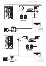
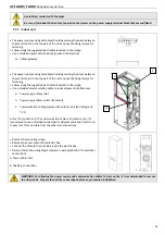
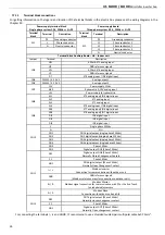
7.5.3 Particular schematic diagram of the plant with hydraulic separator and mixing valve
To the plant circuit
Plant
A
AB
B
Technic water return
Plant remote sensor Mixing water sensor
hydraulic separator
KEY
Circolator pump
Discharge valve
Shut-o
ff
valve
3-way valve motorized
in two-posi
ti
on
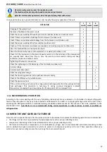
The indicated components are not supplied and their connection should be done by the installer. The remote plant
circuit sensor is always managed. The management of the mixing sensor is possible only with optional module GI2.


