US FLOOR / FLOOR
Minichiller inverter Duo
30
9
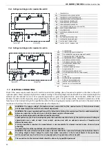
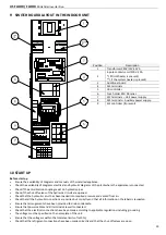
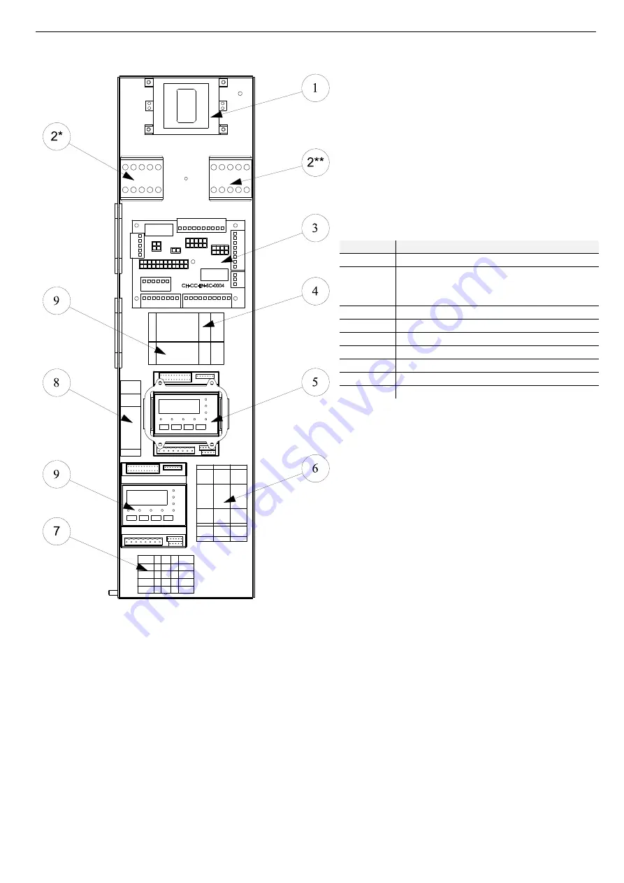
SWITCH BOARD LAYOUT IN THE INDOOR UNIT
Position
Description
1
Transformer 240V/12V-30VA
2
4-pole contactor coil 230 V 20A
*( if DHW heater is present)
**( if the system heater is present)
3
Additional board
4
M5 terminals
5
CB controller
6
Fuse holder BCH 38 series
7
M1 terminals – Unit power supply
8
M3 terminals – Auxiliary power supply-
9
SL2 controller (if present)
10
START UP
Before start-up
•
Ensure the availability of diagrams and manuals of the installed appliance.
•
Check the availability of diagrams electrical and hydraulic diagrams of the plant where the appliance is connected.
•
Check if the anti-vibration couplings exist on hydraulic pipes.
•
Check if the shut-off valves of the hydraulic circuits are opened.
•
Check that the hydraulic circuit has been loaded into required pressure and vented from air.
•
Check that all the hydraulic connections are carried out correctly and that all information on the labels is respected.
•
Ensure that arrangements have been provided to drain condensate.
•
Ensure that power cables and all terminals are well connected.
•
Check that the electrical connections have been made according to applicable regulations including grounding.
•
The voltage must be specified on the nameplate of the unit.
•
Ensure that the voltage is within the tolerance limits of (±10%).
•
Check that the refrigerant connections have been made correctly and that the shut-off valves are open.


