16
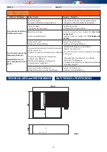
START-UP AND TESTING
AVVIAMENTO E COLLAUDO
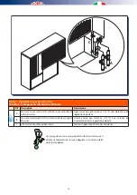
Il collaudo del deumidificatore andrebbe effettuato
contestualmente a quello dell’impianto a pannelli in
funzionamento estivo; la principale verifica da effettuare
riguarda la portata dell’acqua di raffreddamento che
dovrebbe essere di circa 230 l/h (*) quando la temperatura
dell’acqua è di circa 15 °C. Con temperature dell’acqua più basse,
anche le portate devono essere inferiori.
Nel caso in cui non sia possibile misurare la portata dell’acqua
verificare tale condizione controllando la temperatura dell’aria
in mandata accertandosi che:
- ci si trovi nelle condizioni di progetto;
- la macchina sia accesa da almeno 15 minuti;
- siano trascorsi almeno 10 minuti dall’ultima variazione di
portata dell’acqua.
Verificare che la temperatura dell’aria in mandata abbia lo
stesso valore della temperatura in aspirazione (macchina
neutra) ovvero al valore di progetto desiderato.
T
ARIA
IN
MANDATA
= T
ARIA
IN
ASPIRAZIONE
= V
ALORE
DI
PROGETTO
Per raggiungere tale obbiettivo agire sulla portata dell’acqua
variando l’apertura della valvola dell’acqua refrigerata.
(*) Valore di portata con intervallo ammesso fra +20% e -20%
rispetto alla portata indicata. Portata inferiore a 185 l/h può
danneggiare la macchina.
The dehumidifier must be tested together with the panel system in
summer operating mode; the main check which must be performed
regards the
cooling water flow rate
which must be approximately
230 l/h (*) when the water temperature is approximately 15 °C.
By using lower temperatures, water flow rates will be inferior too.
In the event that it is not possible to measure the water flow rate,
verify the condition by checking the
delivery air temperature
,
ensuring that:
- it is within the project conditions;
- the machine has been on for at least 15 minutes;
- at least 10 minutes have passed since the last water flow rate
variation.
Check that the delivery air temperature has the same value
as the intake temperature
(machine neutral)
i.e. the desired
project value.
T
DELIVERY
AIR
= T
INTAKE
AIR
= P
ROJECT
VALUE
In order to reach this objective, adjust the water flow rate, varying
the opening of the chilled water valve.
(*) Flow rate value with +20% and -20% than the mentioned value.
If flow rate is inferior to 185 L/h the unit can be damaged.
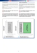
Esempio:
Taria ingresso: 26°C; Taria in uscita: 26°C;
Umidità relativa: 65%; Tacqua: 15°C
Portata batterie: 230 l/h
Example:
T incoming air: 26°C; T outgoing air: 26°C;
Relative Humidity: 65%; Twater: 15°C; Coil flow rate: 243 l/h
1
2
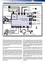
CONSENSO ESTERNO (DEUMIDIFICAZIONE)
L’unità potrà essere avviata solo se saranno stati effettuati
correttamente i collegamenti del consenso remoto (ad es.
umidostato, controllo remoto a microprocessore, ecc.).
A tale riguardo attenersi scrupolosamente a quanto riportato
nello schema elettrico. Nel caso non fosse disponibile alcun
consenso remoto ponticellare i relativi morsetti.
I morsetti del consenso remoto vengono ponticellati in
fabbrica ed etichettati con la scritta UMIDOSTATO: se si
dispone di un dispositivo di consenso remoto rimuovere
tale ponte e procedere al suo collegamento secondo quanto
indicato nello schema.
USCITA ALLARME
Il relé di allarme è normalmente aperto, in caso di anomalia il
contatto si chiude. E’ possibile rendere il contatto normalmente
chiuso togliendo il ponticello denominato NC/NO sul circuito
stampato della scheda.
EXTERNAL CONSENT (DEHUMIDIFICATION)
The unit may only be started up if the remote consent connections
(e.g. humidistat, remote microprocessor control etc.) have been
made correctly.
On this topic, follow the information shown on the wiring diagram
very carefully. If no remote consent is available, jumper the relative
terminals.
The remote consent terminals are jumpered in the factory and
labelled with the wording HUMIDISTAT: if a remote consent
device is available, remove this jumper and connect it as
shown on the diagram.
ALARM OUTLET
Alarm relay is usually open, in case of any anomaly the contact
closes. It is possible to keep the contact close by removing the wire
either from NC or from NO on the circuit of the board.
Summary of Contents for RNW 214-I
Page 2: ......
Page 10: ...10 2 3 1 2 POSITIONING OF THE DEHUMIDIFIER 2 INSERIMENTO E FISSAGGIO DEL DEUMIDIFICATORE ...
Page 26: ...26 NOTES ...
Page 27: ......


