29
US
E
UTILIZZ
O
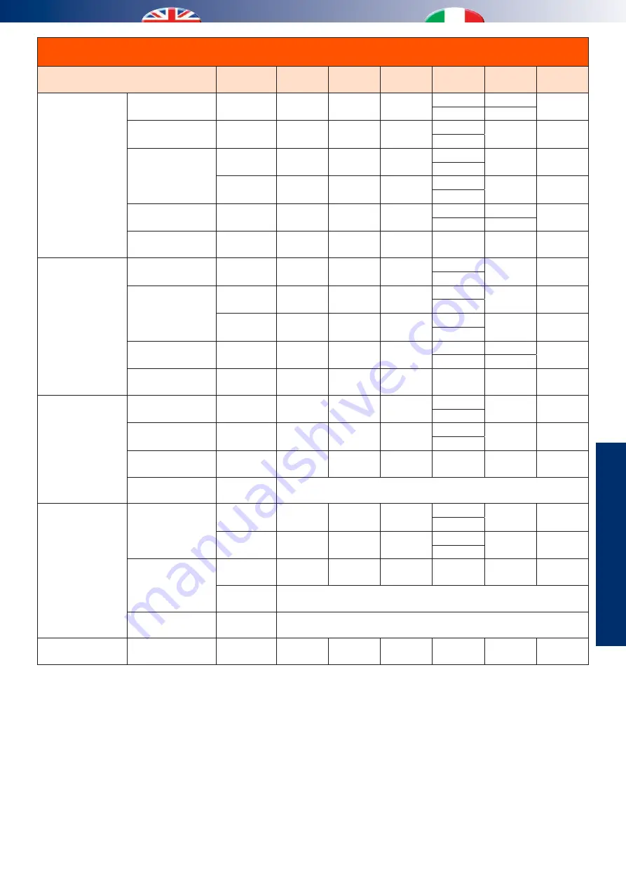
Advanced functionings table
Tabella funzionamenti avanzati
Combined functioning
Funzionamento combinato
Season
Stagione
VI
VE
CO
VA
PI
SFC
Recirculation
Ricircolo
Renewal
Rinnovo
Sum / Win
Est / Inv
PA
PR
-
/
-
-
ON
ON
Dehumidification
Deumidificazione
Summer
Estate
PA
-
ON
/
ON
-
ON
Integration
Integrazione
Summer
Estate
PA
-
ON
/
ON
-
ON
Winter
Inverno
PA
-
-
/
ON
-
ON
Boost
Sum / Win
Est / Inv
PB
PB
-
/
-
-
ON
ON
Free-cooling
PRE / POST
Sum / Win
Est / Inv
PA
PF
-
-
-
ON
Renewal
Rinnovo
Dehumidification
Deumidificazione
Summer
Estate
PA
PR
ON
/
ON
-
ON
Integration
Integrazione
Summer
Estate
PA
PR
ON
/
ON
-
ON
Winter
Inverno
PA
PR
-
/
ON
-
ON
Boost
Sum / Win
Est / Inv
PB
PB
-
/
-
-
ON
ON
Free-cooling PRE /
POST
Sum / Win
Est / Inv
PR
PR
-
-
-
ON
Dehumidification
Deumidificazione
Integration
Integrazione
Summer
Estate
PA
-
ON
/
ON
-
ON
Boost
Summer
Estate
160 m
3
/h 160 m
3
/h
ON
/
ON
-
ON
Free-Cool. PRE
Summer
Estate
160 m
3
/h 160 m
3
/h
ON
ON
ON
ON
Free-C. POST
Summer
Estate
Dehumidification only, switch off Free-cooling
Solo deumidificazione, Free-cooling inibito
Integration
Integrazione
Boost
Summer
Estate
160 m
3
/h 160 m
3
/h
ON
/
ON
-
ON
Winter
Inverno
160 m
3
/h 160 m
3
/h
-
/
ON
-
ON
Free-Cool. PRE
Summer
Estate
160 m
3
/h 160 m
3
/h
ON
ON
ON
ON
Winter
Inverno
Free-cooling only, inhibited Integration
Solo Free-cooling, Integrazione inibita
Free-C. POST
Sum / Win
Est / Inv
Free-cooling only, inhibited Integration
Solo Free-cooling, Integrazione inibita
Boost
Free-cooling
PRE / POST
Sum / Win
Est / Inv
PB
PB
-
-
-
ON
VI = Ventilatore immissione
VE = Ventilatore espulsione
CO = Compressore
PI = Pompa impianto
VA = Valvola acqua (“/” = valvola non abilitata)
SFC = Serranda free-cooling
PA = Portata Ambiente
PR = Portata Rinnovo
PB = Portata Boost
PF = Portata Free-cooling
VI = Inflow fun
VE = Discharge fun
CO = Compressor
PI = System circulation pump
VA = Water valve (“/” = valve disabled)
SFC = Free-cooling dumper
PA = Room flow rate
PR = Renewal flow rate
PB = Boost flow rate
PF = Free-cooling flow rate
Summary of Contents for Unit Comfort UC 300-M
Page 2: ......
Page 22: ...22 7 OPTIONAL DUMPER INSTALLATION INSTALLAZIONE SERRANDE OPZIONALI 3 5 6 7 2 1 4 8 9 ...
Page 57: ...i INFO 57 NOTES ANNOTAZIONI ...
Page 58: ...58 NOTES ANNOTAZIONI ...
Page 59: ......


