6 INS
T
ALL
LIMIT
S
WIT
CHES
1.
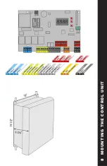
Locate the control housing containing the Thalia
UL panel.
2.
At this time, plan where you would like to run the
wiring into the housing and predrill for stress-relief
connectors.
NOTE! Be careful not to damage the
panel when drilling into the housing! It is advisable
to remove the panel while drilling.
3.
Mount the housing securely, using either screws
or drywall anchors (not supplied). Be careful not to
damage any wires or components of the board. (See
“Typical System Overview” for suggested location of
the housing)
MOUNTING THE CONTROL UNIT
7
CONTR
OL
UNIT
MOUNTING
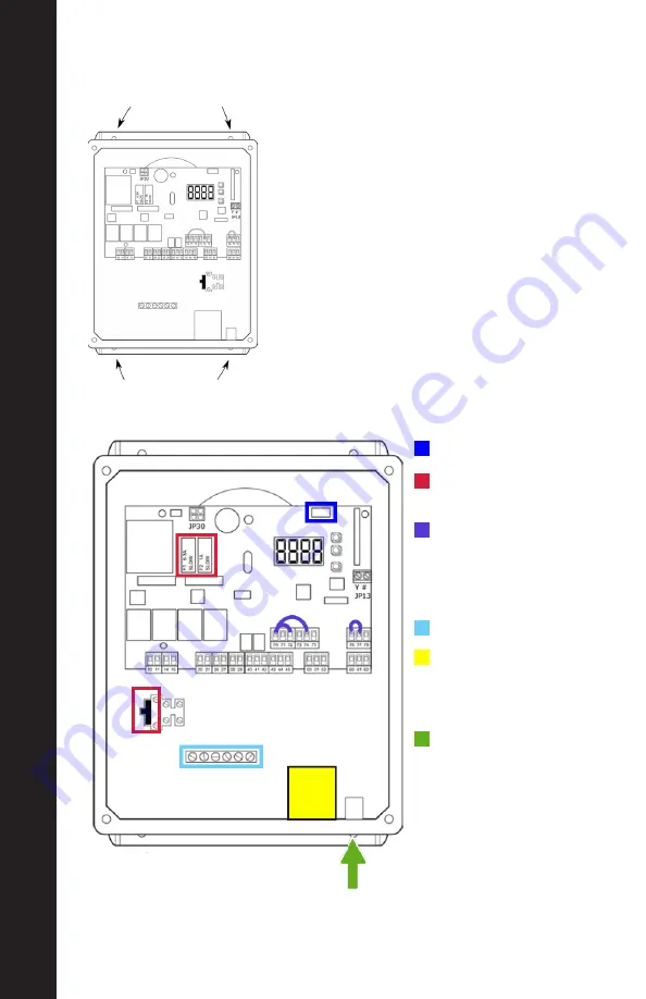
CONTROL UNIT SPECIFICATIONS
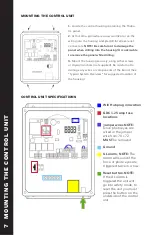
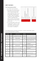
Wifi Hub plug in location
GDC 1.25 amp fuse
locations
Jumper wires NOTE:
Once photo eyes are
wired in the jumper
wire from 70 + 72
MUST
be removed
Ground
UL alarm, NOTE:
The
alarm will sound if the
force or photo eyes are
triggered twice in a row
Reset button. NOTE:
If the UL alarm is
triggered the unit will
go into safety mode, to
reset the unit you must
press the button on the
underside of the control
unit.
7
MOUNTING
THE CONTR
OL
UNIT


