生活美好,臂不可少
http://www.realman-robotics.com
24
5
drag teaching button in
green
1
long-hold press, then the robot begins the
drag teaching mode
6
trajectory repetition
button in blue
1
short-term press, then the robot repeats the
trajectory recorded by dragging
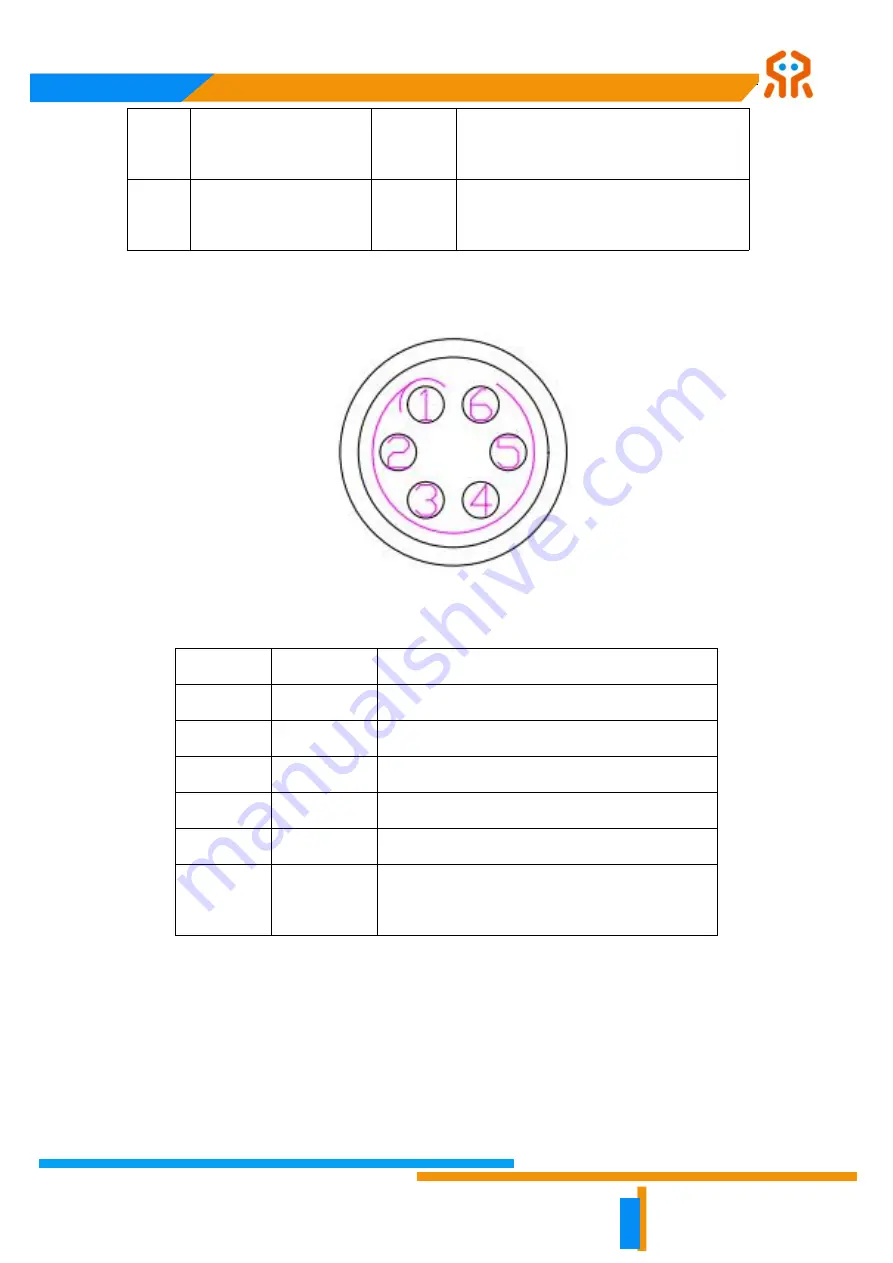
The tool end interface provides a 9-pin aviation plug to be connected. Its pins and
functionalities are shown below.
Fig. 5-6 Pin definition of aviation plug on tool end.
Pin #
Wire Color
Functionality
1
yellow
RS485_A
2
white
RS485_B
3
red
digital interface 1 (DI1/DO1)
4
black
digital interface 2 (DI2/DO2)
5
green
power GND
6
blue
power output: 0V/5V/12V/24V, which is
programmable
Note that multiplexing function in the above table can be switched by programming.
The factory default pin 3 and 4 are the digital input channel (DI1 and DI2), and the
power output of the pin 6 is 0V, which is programmable.
5.3.1 Digital I/O Input
There are two digital input channels, and their electrical characteristics are shown in
the table below.


