RealMan (Beijing) Intelligent Technology Co., Ltd.
43
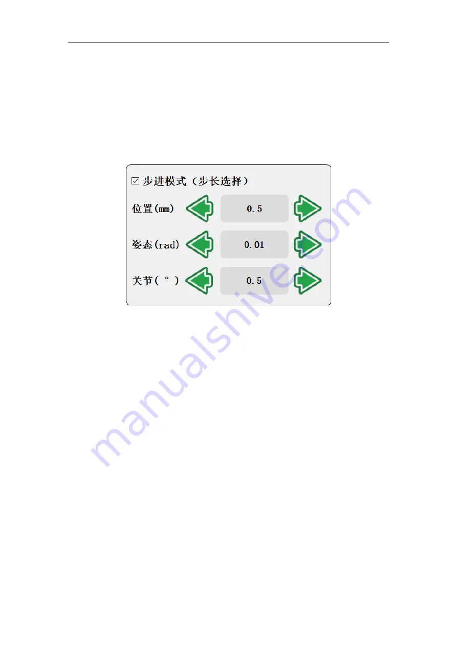
the movement, it will stop once released.
➢
“Pose”: Represents the step size to control the motion angle of the end, in
radians, at the pose control panel.
➢
“Joint”: Indicates the step to control the motion angle of each joint, in degrees,
at the joint control panel.
➢
Step control is only effective for robot end and joint control.
Fig. 8-20 Step mode demo.
8.2.13 Robot Position and Pose Parameter Display
The position (X, Y, Z) denotes the center of tool flange (the selected tool coordinate
system) in the selected coordinate system (from one of Base coordinate system, end
coordinate system, and customized coordinate system). The pose (RX, RY, RZ)
expresses the rotation arc relative to the selected coordinate system, resulted from
rotating along the selected coordinate system in a certain order.


