background image

RealMan (Beijing) Intelligent Technology Co., Ltd.


34 


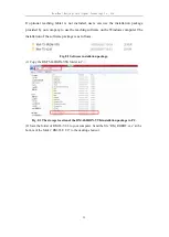
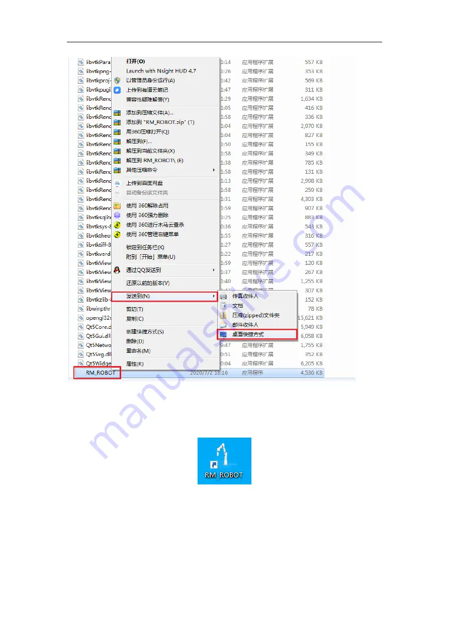
Fig. 8-4 Desktop shortcut creation. 

(3) 

Double-click  the  shortcut  generated  on  the  desktop  to  run  the  teaching  software 

interface. The teaching software shortcut is shown as follows. 


Fig. 8-5 The shortcut of the teaching software. 

8.2 Robot Teaching 

The teaching panel is used for robot teaching operation. Users can move the robot joints 

by clicking on the icon on the panel. This panel also demonstrates the information about 

the robot's movements to the user. 

Summary of Contents for RM75-B

Page 1: ...RealMan Beijing Intelligent Technology Co Ltd 1 RealMan RM75 B Robot Manual V1 8 RealMan Beijing Intelligent Technology Co Ltd...

Page 2: ...2 2020 06 15 Add intro of graphic online coding V1 3 2020 07 21 Add intro of bottom electrical board V1 4 2020 08 20 Revise intro of aviation plug order on the electrical board of the robot arm end V1...

Page 3: ...19 5 2 Controller I O 20 5 2 1 Digital Input 22 5 2 2 Digital Output 23 5 2 3 Analog Input 23 5 2 4 Analog Output 23 5 3 The Tool End Interface Board 23 5 3 1 Digital I O Input 25 5 3 2 Digital I O O...

Page 4: ...oject Load 46 8 3 3 Project Creation 47 8 3 4 Project Save 47 8 3 5 Project Content Display 48 8 3 6 Automatic Setting of a Programmable Point 48 8 3 7 Manual Setting of a Programmable Point 49 8 3 8...

Page 5: ...RealMan Beijing Intelligent Technology Co Ltd 5...

Page 6: ...eded Users can build their own robot control system by accessing the APIs of our collaborative RM75 B Besides this product also provides programmable operating software through which users can monitor...

Page 7: ...safety warning signs we provide for your safety It is crucial and the instructions shall be followed Table 2 Warning Signs and Instructions Sign Instruction An impending hazardous electrical condition...

Page 8: ...tem for the first time Other safety related information is introduced in other sections of the manual However it is impossible to cover everything In practical applications specific issues need to be...

Page 9: ...applied to prevent unauthorized personnel from changing or setting safety related hyperparameters After the safety related factors are modified the related safety features need to be double checked 8...

Page 10: ...e level Please read and understand the manuals for all equipment used during the installation 10 Do not modify the robot Non authorized changes to the robot can create dangers that the integrator cann...

Page 11: ...and installation of the complete system in accordance with the laws regulations and safety codes and standards of the host country or region Risk assessment is one of the most important tasks that mus...

Page 12: ...ty guards requires first a risk assessment to determine whether the associated hazards pose an unacceptable risk including but not limited to The use of sharp actuator or tool connectors which may be...

Page 13: ...nnel and equipment while it is programmed 2 Transportation and Precautions When the robot is hoisted proper measures and positioning should be taken for the moving parts so as not to cause accidental...

Page 14: ...o us as RealMan Beijing Intelligent Technology Co Ltd in accordance with the regulations of the manual Assure the required safety level for maintenance and repair Comply with national or regional safe...

Page 15: ...y features as soon as maintenance is accomplished 3 Keep maintenance records in the technical documents related to the whole robot system 4 The controller has no parts that users can repair by themsel...

Page 16: ...as RealMan Beijing Intelligent Technology Co Ltd reserves the right to charge the customer for the replacement or repair Outside the warranty period we as RealMan Beijing Intelligent Technology Co Ltd...

Page 17: ...ijing Intelligent Technology Co Ltd 13 Use the product in radioactive equipment biological test equipment or in the use that we as RealMan Beijing Intelligent Technology Co Ltd judge to be dangerous 1...

Page 18: ...a human arm that has seven rotating joints each representing one degree of freedom DoF As shown in Figure 5 2 the robot joints include shoulder joint 1 shoulder joint 2 shoulder joint 3 elbow joint 4...

Page 19: ...on plug located at the lower left corner of the controller panel In the 2 core power cable the brown core is the positive power supply and the blue core is the negative power supply The robot arm also...

Page 20: ...ower cable 3 extension plug outlet the RS485 I O etc interface of the controller 4 WIFI Bluetooth wireless communication 5 USB port 1 upgrade software import and export files 6 USB port 2 control the...

Page 21: ...wn in the table below Color Symbol Functionality Other 1 blue striped brown purple 5V 5 volts output 2 yellow brown green brown GND Ground 3 red brown 12V 12 volts output 4 purple brown CAN_H CAN bus...

Page 22: ...l digital output channel 0 12 volts 26 black DGND External digital ground Robot arm has I O ports whose quantities and functionalities are shown below digital output DO 4 ports configurable from 0 to...

Page 23: ...wer Vin 0 5 24 V 5 2 3 Analog Input The controller has 4 analog input channels or ports Its voltage range is 0 10V Its electrical characteristics are shown in the table below Analog input Min Typical...

Page 24: ...ity 1 power output 1 configurable from 5V 12V 24V switch on and off is controllable 2 digital output 2 the reference level is consistent with the power output 3 digital input 2 the reference level is...

Page 25: ...ut 5V 12V 24V switch on and off is controllable Note that multiplexing function in the above table can be selected by the dialing switch on the interface board circuit board When switching the functio...

Page 26: ...ol The electrical characteristics are shown in the table below Digital Output Min Typical Max Unit input power Vin 0 24 V 5 3 3 Analog I O Input There is one analog input channel at the tool end and i...

Page 27: ...cal characteristics are shown in the table below Hyperparameter Min Typical Max Unit power voltage 0 24 V power current 800 1000 mA 5 3 6 Communication Interface The tool end outputs one RS485 communi...

Page 28: ...e must not vibrate Please refer to Section 11 Technical Specifications document for specific load carrying capacity A safety assessment must be carried out after each installation of the robot and ope...

Page 29: ...ion range of joint 6 128 and rotation range of joint 7 360 Fig 6 2 The schematic of the movement range of the robot 6 4 Robot Installation When installing on the base 4 M6 bolts are used to fix the ro...

Page 30: ...period of time it may be damaged Robots should not be installed in water or wet conditions unless they are declared to have IP67 protection rating Tipping hazard if the robot is not securely position...

Page 31: ...is no external device just connect the power cord refer to Section 5 1 2 for specific interface description Fig 7 1 Robot power socket 7 2 Power On Connect the power cable to the power socket Check t...

Page 32: ...ming 8 1 Introduction The optional teaching tablet or pad contains the RM75 B teaching software If the teaching tablet is not included you can choose any computer of Windows operation system to instal...

Page 33: ...tware on the Windows computer The installation of the software package is as follows Fig 8 2 Software installation package 1 Copy the RM75 B IRON VTK folder to C Fig 8 3 The storage location of the RM...

Page 34: ...ching software interface The teaching software shortcut is shown as follows Fig 8 5 The shortcut of the teaching software 8 2 Robot Teaching The teaching panel is used for robot teaching operation Use...

Page 35: ...bar 4 robot arm emergency stop button 5 position control 6 pose control 7 joint control 8 operation mode selection 9 operation coordinate selection 10 tool coordinate selection 11 3D simulation model...

Page 36: ...s that the power supply of the robot arm is in the open status and gray represents that the power supply of the robot arm is in the off status Fig 8 8 The robot arm power button 8 2 3 Menu Bar Click t...

Page 37: ...oves after releasing it the robot stops moving Likewise same thing with the rest of the buttons Fig 8 11 The position control panel 8 2 6 Pose Control The pose of the robot arm end can be controlled b...

Page 38: ...nt from bottom to top is named as joint 1 to joint 7 which corresponds to the seven joints of the robot Users only need to use the joint control buttons on the teaching software panel to control the r...

Page 39: ...on Its parameters and the moving status image of the robot arm will be displayed on the interface When the simulation mode is selected the robot does not move but its 3D simulation To finalize a robot...

Page 40: ...l take the coordinate system as shown in Fig 8 15 as the Base coordinate system Users can also create their own operation coordinate system as the reference direction of the robot movement to meet act...

Page 41: ...wn menu and select the coordinate system of the flange center by default see Fig 8 17 Users can also set customized tool coordinate systems Assuming that tool1 is the tool coordinate system set by the...

Page 42: ...or touching the tablet interface according to the needs Fig 8 19 The 3D simulation model 8 2 12 Step Mode Setting To increase the teaching accuracy step control model is used which can make the contr...

Page 43: ...trol is only effective for robot end and joint control Fig 8 20 Step mode demo 8 2 13 Robot Position and Pose Parameter Display The position X Y Z denotes the center of tool flange the selected tool c...

Page 44: ...lso freely set the initial position and pose of the robot according to the descriptions in the section of the initial pose calibration Section 8 4 2 4 through the teaching software Release the button...

Page 45: ...o realize the complex robot movement Fig 8 24 The online programming panel Table 6 Online programming panel Name 1 project file path selection button 2 import project button 3 new project button 4 sav...

Page 46: ...blocks keys are described as follows in the order shown in Table 6 8 3 1 Project Selection For the created project click the Select Project button then select the project path and click Open and the f...

Page 47: ...the gray box 3 Click Load button and the project will appear in the project content display area Fig 8 26 The project load panel 8 3 3 Project Creation After clicking button the project content displa...

Page 48: ...ine MOVEL linear motion command Move the robot TCP to a given target point along a straight line It is suitable for the occasions where the high precision of the path is required such as cutting gluin...

Page 49: ...oint angles of the target pose When MOVEL or MOVEC is selected it moves in Cartesian space The text box below it displays the position and pose data of the target When you select Wait it waits a certa...

Page 50: ...a programmable point 8 3 8 Insert Points Before the Current After recording the programmable points manually or automatically clicking the button will insert the newly created points before the curren...

Page 51: ...the project content display column and add it after the line of program 8 3 10 Copy Click the button to copy the instruction and location information of the selected line 8 3 11 Paste Click the butto...

Page 52: ...int Check Automatic edit and click the button the panel will automatically jump to the robot teaching interface Fig 8 32 Automatic editing a programmable point You can re teach the points After the te...

Page 53: ...point Click the button to record the position of the re taught point and complete the point editing Fig 8 34 Updating a programmable point With the final point parameters known you can check Manual E...

Page 54: ...e deleted in the display area on the left and then click button Fig 8 36 Deleting a programmable point 8 3 14 Move the Joint to the Current First click the target point at the left programmable point...

Page 55: ...ps and then enter the number of loops on the right side 8 3 17 Start the Trajectory Tracking When online programming project is completed click the trajectory start point on the left side display area...

Page 56: ...t of the trajectory at the left status area and the background color turns to green Then the user clicks the button and the button changes to a button with the pause function to complete the trajector...

Page 57: ...rajectory tracking in order to avoid accidents caused by mishandling all the function of the interface are locked and cannot be used After pressing keys at the interface can be used properly 8 3 21 Te...

Page 58: ...the track Teaching by dragging has four modes current loop position only pose only and pose position combination of four ways the latter three modes need six axis force sensor Fig 8 39 Teaching by dr...

Page 59: ...ernal communication The network name is the WIFI name of the controller and the network password is the password of the controller s WIFI After clicking the Set button the controller will conduct netw...

Page 60: ...e When the teaching software and the controller need to be connected directly through the Ethernet port the controller will communicate through the Ethernet port 2 IP address 192 168 1 18 port number...

Page 61: ...ction between the computer and the controller the local network IP needs to be configured in the same network segment The configuration is shown below 1 Open Open Network and Sharing Center at the low...

Page 62: ...Fig 8 43 Local connection 3 Click the Properties button in the dialog box that pops up Fig 8 44 Select the Properties button of local connection 4 In the pop up dialog box select Internet Protocol Ver...

Page 63: ...g to the following figure Click OK button to complete the local network setting after the configuration Fig 8 46 The Internet IP address 6 Click the Configuration System Configuration Connect Robot Ar...

Page 64: ...of the robot arm end as shown in the figure below Fig 8 48 The safety configuration 1 Joint Configuration Select joints 1 7 in the left drop down box corresponding to the seven joints from bottom to...

Page 65: ...ikewise 1 Select joint 1 from the leftmost option 2 Click the Enable button on the right Fig 8 50 Enable a joint Set the origin when the joint is in the disenabled status click the button and set the...

Page 66: ...must be reset Example of setting origin Set the origin of joint 1 and the origins of other joints can be set likewise 1 Select joint 1 from the leftmost option 2 Click the Disenable button on the righ...

Page 67: ...ot arm After the network connection between the teaching software and the robot controller is established this feature will automatically update the TCP parameters of the current robot and the user ca...

Page 68: ...s of the robot must be recalibrated otherwise the situation of false collision will also occur 4 Installation Method There are three ways to install the robot arm i e lifting mounting and side mountin...

Page 69: ...matically calculate the current tool information according to the 6 points After the calculation is completed it will be sent back to the teaching software and displayed in the tool list In addition d...

Page 70: ...libration we need to enter the weight and center of gravity position of the end tool to make the tool parameters at the end of the robot arm more durable 8 4 2 3 Calibration of the Operation Coordinat...

Page 71: ...tware and displayed in the coordinate system table In addition due to the memory limitation of the robot controller only 10 operation coordinate systems can be saved So please make sure that the numbe...

Page 72: ...nformation System information includes controller status and joint status as well as system logs System information including controller input voltage output current temperature pose and error code Ro...

Page 73: ...n the IO interface of the teaching software as shown in the figure below Fig 8 59 The I O configuration interface Digital Input This section displays the status of digital IO inputs with gray circles...

Page 74: ...O Configuration In the IO interface of the tool panel of the teaching software the IO status and configuration of the tool can be displayed The output voltage of the tool end can be switched And simpl...

Page 75: ...from the robot arm end interface board which can be configured with 0V 5V 12V and 24V External equipment by default gripper and dexterous hand can be added at the tool end and other devices can be add...

Page 76: ...le point i e point1 5 Go to Teaching the Robot panel and move the robot to the first target programmable point of point1 Fig 9 2 Teaching the robot to point1 through the teaching panel 6 Back to Onlin...

Page 77: ...8 Insert the second programmable point with a control method of e g MOVEL 9 Name it as point2 Fig 9 3 Automatic setting a programmable point i e point2 10 Go to Teaching the Robot panel and move the...

Page 78: ...point3 14 Go to Teaching the Robot panel and move the robot to the third programmable point i e point3 15 Back to Online Programming interface and click Record the Current Point button 16 Click the Ad...

Page 79: ...method is MOVEJ the Angle Setting will appear below 3 Input the name of point5 4 Set the joint angles to the desired joint angles Note the joint angles filled in shall not exceed the joint limit value...

Page 80: ...it as the control method 8 Give a name i e w 9 Set the time to 3 seconds 10 Click Record Point button 11 Click the Add to After button to add the point to the list on the left Fig 9 8 Manual setting t...

Page 81: ...Point button 16 Click the Add to After button to add the point to the list on the left Fig 9 9 Manual setting a programmable point i e point6 Edit the point Suppose to make changes to an existed progr...

Page 82: ...point and click the Select Point button Fig 9 11 Automatic editing an existed point 6 Enter the next interface move the joint to the target position and click OK button The target returns to the prev...

Page 83: ...the pause press the Continue button to continue the movement 3 Press the Single Step button to perform single step movement 4 Press the Stop button to stop the movement To prevent accidents manually...

Page 84: ...ough the USB flash drive The specific operation steps are as follows 1 Turn off the power supply of the robot arm 2 Copy the bin upgrade file provided by the manufacturer to the bin directory of the U...

Page 85: ...patient Please do not power off during the update 11 Technical Specifications Robot RM75 B DoF 7 Payload 5kg 11lbs Weight 7 8kg 17 2lbs Repeat Ability 0 05mm 0 002in Reach 610mm 24in Voltage DC 24V ra...

Reviews: