Rear View Safety
16
GRIDLINES
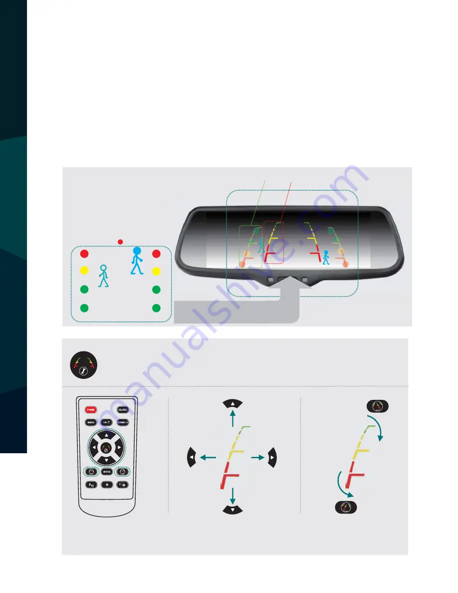
Long press the “Settings” (middle) button on the remote to enter grid
line adjustment mode. Press the “Settings” button again to toggle be-
tween left/right grid lines. Use the “UP/DOWN/LEFT/RIGHT” buttons to
adjust grid line location, and the rotation buttons to adjust grid line
angle.
Chapter three: Adjustable Guideline
Generally, to help drivers es
�
mate the distance from obstacles, there are three lines for
reference -red, yellow and green. Those three lines are displayed on the monitor when car is
reversing. The green line is 3m from the back of car and the yellow line is 2m. The distant red
line is 1m from the backside of car while the closed red line is 0.4m. Both reference lines on
the le
�
and right should leave 0.2m space from the car.
Regular guide line is
xed. But installa
�
on sites of cameras are di
ff
erent as well as car size. The
xed guide line is not accurate enough for drivers. There will be a great di
ff
erence between
regular and
xed guide lines and car's real guide lines, especially when camera is mounted on
the le
�
or right side of car backside. It may cause accidents.
20CM
20CM
3.1 About guide line
3.2 What the regular guide line is
3.3 How to adjust the guide line
Note: keep the remote control 05.m-1.0m from rear view mirror when you use the remote
to adjust the parking lines.
Press the bu
Ʃ
on to choose L or R adjustable guide line
Remote control
Move the guide line
Rotate the guide line
Clockwise
Up
Right
Down
Le
�
An
�
-clockwise
According to the site of standard reference line, we can put reference objects such as desks
in the back side of the car. Compared with the marked reference objects, we can adjust the
sites and angles of two guide lines are displayed on the monitor. You will get the accurate
and safety guide lines once it coincides with the reference objects.
Press
se
�
ng
bu
�
on
to
enter
“guide
line
adjustment” mode
.
The system is defaulted to
adjust le
�
guide line
rst.
Press the bu
�
on again to switch to adjust the right guide line.
The
up ,
down , le
�
and
right bu
�
ons
are
to adjust
the corresponding loca
�
on
of
guide
lines
.
The
clockwise rota
�
on
and contra rota
�
ng bu
�
ons
are
to
adjust
the
angles of
guide
lines
.
It
is
easy
to operate
and
calibrate
.
A
�
er
nishing calibra
�
on, switch the
reverse gear to save the informa
�
on.
10
9
R
L
Wrong
posi
Ɵ
on
Right posi
Ɵ
on
Display
on
the
monitor


