10
7. Assembly Instructions
- cont.
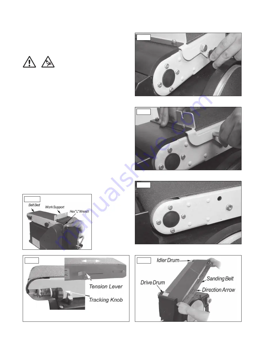
Installation of the Sanding Belt,
Tensioning & Tracking
Warning: To avoid injury from accidental starting, make sure the
machine is unplugged before aligning. On the smooth side of
the sanding belt, you will find a directional arrow. The sanding
belt must run in the direction of this arrow so that the spliced
joint does not come apart.
1. Remove two lock knobs of the sander belt work support,
Fig 7.8
.
2. Remove the work support lock pin,
Fig 7.9
.
3. Remove the work support,
Fig 7.10
.
4. Loosen the hex head socket screw, Fig
7.11
, to allow the belt bed to
be raised.
5. Slide tension lever to the left to release the belt tension,
Fig 7.12
.
6. Place the sanding belt over the drums with the direction arrow pointing
as shown in
Fig 7.13
. Make sure the belt is centred on both drums.
7. Slide tension lever to the right to apply belt tension,
Fig 7.12
.
8. Tighten hex socket screw when bed is in desired position.
9. Reinstall the work support.
10. Rotate the belt by hand in the direction of the arrow. If the belt tends to
slide off the idler drum or drive drum, adjust the belt using the tracking
knob,
Fig 7.12
until the belt runs centrally on both drums.
11. If the sanding belt moves toward the disc, turn the tracking knob
clockwise 1/4 turn.
12. If the sanding belt moves away from the disc, turn the tracking knob
anti-clockwise 1/4 turn.
Fig 7.8
Fig 7.9
Fig 7.10
Fig 7.13
Fig 7.12
i
Kg
i
Kg
Fig 7.11


