27
14. Maintenance - Cont.
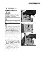
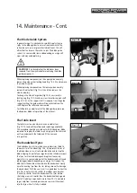
7. Check the blade tracking on the newly fitted blade by
turning the upper wheel by hand. To track the blade
loosen the locking knob on the back of the machine
and turn the tracking knob clockwise to move the blade
back and anti clockwise to move the blade forward. The
blade should run as close to the centre of the bandwheel
as possible. When the blade is tracked correctly make a
final check to ensure that the blade tension is adequate
for the type of blade being used.
8. Re-set the blade guides.
9. Close and lock both the bandwheel doors, refit the fence
rail and rip fence before re-connecting the power supply.
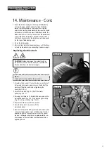
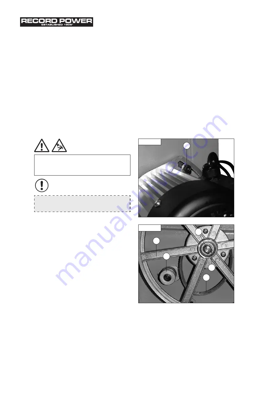
1. To replace the drive belt slacken the tension on the belt
by loosening the motor pivot screw on the back of the
machine, lifting the motor and re-tightening the
screw (Fig. 14.3, A).
2. Ease the drive belt (Fig. 14.4, B) off the motor
pulley (Fig. 14.4, C).
3. Ensuring that there isn't a blade fitted now remove the
lower bandwheel (Fig. 14.4, D) by releasing the circlip
(Fig. 14.4, E) from the hub (Fig. 14.4, F).
4. Remove the old belt and fit the new one.
5. Once the drive belt is in place re-fit the
lower bandwheel.
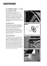
6. Now tension the drive belt by loosening the motor pivot
screw and lowering the motor until adequate tension is
applied. Re-tighten the motor pivot screw. The correct
tension is achieved when there is approximately 6 mm
of movement of the belt when reasonable pressure is
applied by hand.
CAUTION!
Before carrying out any adjustments or
maintenance ensure that the machine is isolated and
disconnected from the electricity supply.
Note:
Circlip pliers are required for this procedure.
Replacing the Drive Belt
Fig. 14.3
A
B
C
D
F
E
Fig. 14.4
i
Kg
i
Kg
i
Kg
Summary of Contents for BS10
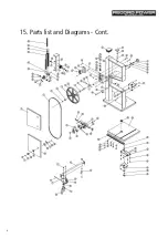
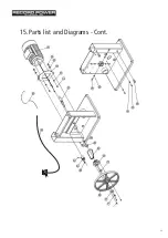
Page 32: ...32 15 Parts list and Diagrams Cont ...
Page 33: ...33 15 Parts list and Diagrams Cont ...
Page 35: ...35 ...


