15
A
A
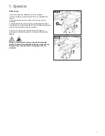
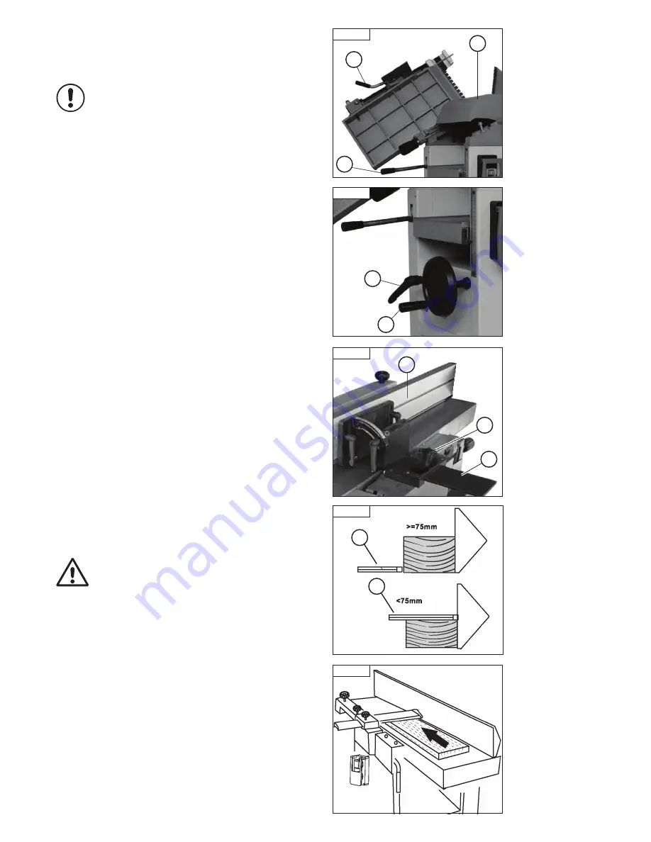
Fig. 5.9
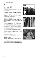
Fig. 5.6
A
B
C
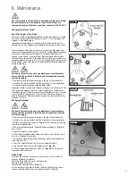
Fig. 5.7
B
A
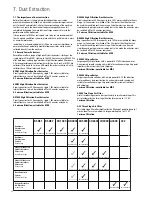
Fig. 5.8
C
B
A
Fig. 5.10
Changeover from Planing to Thicknessing
Warning:
Remove the planer fence before changeover.
1. Open the table lock (A -
Fig. 5.6
) of the out-feed table and pull out the
lever until it stops.
2. Now lift up the out-feed table.
3. Be sure the out-feed is fully raised and tilted by more than 90
o
.
4. Now you can raise the in feed table in the same way.
5. Finally, raise the combined extraction hood (C -
Fig 5.6
)
to cover the cutter block.
6.Release (upwards) the thicknesser feed clutch lever (B -
Fig 5.6
).
7. Proceed in reverse order when closing the planer table.
Attention:
Ensure that the thicknessing table is at least 160 mm below
the cutterblock to allow the extraction hood to move freely between the
surface planing and thicknessing positions.
Adjusting the height for thicknessing
1. Measure the thickness of your work-piece.
2. Unscrew the lock lever (A -
Fig 5.7
) that clamps the thicknessing table.
3. Now raise the thicknessing table upwards via hand-wheel (B -
Fig 5.7
)
to the desired height.
4. Retighten lock lever (A -
Fig 5.7
) to clamp the thicknessing table.
Attention:
The maximum depth of cut is directly related to
following points:
• The width of the work-piece.
• Type of wood (hardwood or softwood)
• Wood dampness
• Condition of planer blades
• Planer blade
Rear Planer Fence Guard
This guard (A-
Fig 5.8
)
is an integral part of the planer fence (B -
Fig 5.8
),
so it will always be positioned over the planer cutter block. If necessary,
adjust the planer fence across the cutter block by unscrewing the star knob
screw (C -
Fig 5.8
).
Working techniques
Caution: Never place your hands on the work-piece over the
planer cutter block.
Surface Planing
Cover the entire cutter block with protective bridge guard A and set it only
slightly higher than the thickness of the workpiece.
At a work-piece thickness of 75 mm or greater, move the bridge guard up to
the side of work-piece and let it rest on the planing table,
(Fig 5.9)
. When
the thickness of the work piece is less than 75 mm, the guard should be
positioned above the work piece
(Fig 5.10)
.
Your hands should be laid out flat onto your work-piece and push it forward
to the cutter block. Allow your hands to glide over the planer bridge guard
one by one. As soon as it is possible, push your work-piece with
both hands on the out feed table. Bring back the plank over the planer
bridge guard into starting position to perform a second pass.
Ensure that your hands are placed on the work-piece in a closed position
with the thumbs against the closed hands.
5. Operation
i
Kg
i
Kg
Summary of Contents for PT107
Page 29: ...29 10 Parts List Diagrams cont ...
Page 33: ...33 ...


