16
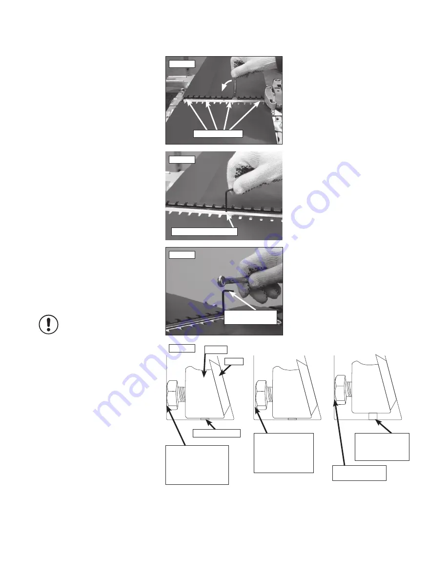
Centre jacking screw
5. Machine Set Up
- cont.
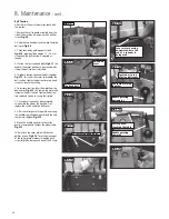
5.3 How to adjust Planer Knives
The wedge and knives are now ready to be set.
Turn the four locking nuts anti-clockwise
Fig 5.7
and tighten enough to hold the knife, but not so
hard that it cannot move. The principle is simply:
To raise the height of the knife tighten
the jacking screw, to lower slacken off
the jacking screw.
Setting planer knives is absolutely crucial to
accurate results, incorrectly set knives result in
a machine that either won’t plane at all, planes
tapers, or takes scoops (snipe) out of the end of
the work. if the blades are set too low the wood
will foul on the edge of the outfeed table, or
start to cut and then taper off. If the blades are
too high it will plane adequately but then take a
scoop (snipe) out at the end.
Listed below are a few hints to bear in
mind when setting the knives.
• The knives are set to the outfeed table, the
infeed table should be lowered out of the way.
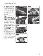
• Adjust the centre jacking screw first and
tighten the two middle locking nuts.
Fig 5.8.
Now adjust either side to match the centre. By
making the adjustments in this order it should
remedy any slight distortion which is sometimes
present in planer knives if they have been held
by magnets when being ground.
• When tightening the jacking screws do so
very delicately, even a tiny fraction of a turn can
make a big difference as the jacking points are
very sensitive.
• When slackening the jacking screws it may be
necessary to tap the top of the hex key to get
this point to seat and lower the knife
Fig 5.9
• If the jacking screw becomes difficult to turn
when raising the knife it is because the space
allowed by the locking nut has been adjusted
out
Fig 5.10
, simply turn the relevant locking
nut in a little so the wedge has a little more
space to slide into.
• Whether adjusting the locking nuts or jacking
screws, do so in tiny increments. It is easier to
set the knives with the locking nuts being as
tight as possible whilst still allowing movement.
In general the procedure is:
1. Tighten jacking screw a fraction
2. Slightly back off locking nut.
3. Tighten jacking screw a little more.
4. Check setting.
5. Repeat until setting has been
achieved.
4 x locking nuts
Fig.5.7
Fig.5.8
Fig.5.9
Tap the top of the
hex key
Fig.5.10
Locking nut against
cutter block. Note; if
the jacking screw is
tightened there is no
space for the wedge
to slide.
Locking nut wound
in slightly, leaving
gap for wedge to
slide into when
jacking screw is
tightened
Locking nut now
tight again
Jacking screw
tightened sliding
wedge & knife
upwards
Knife
Jacking screw
Wedge
i
Kg
Summary of Contents for PT260
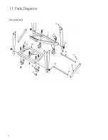
Page 28: ...28 11 Parts Diagrams Stand Wheel Kit ...
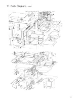
Page 29: ...29 11 Parts Diagrams cont ...
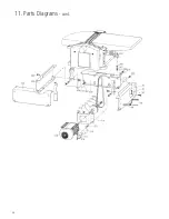
Page 30: ...30 11 Parts Diagrams cont ...
Page 34: ...34 ...
Page 35: ...35 ...


