18
6. Operation & Planer Thicknesser Practice
6.1 Chip removal when planing
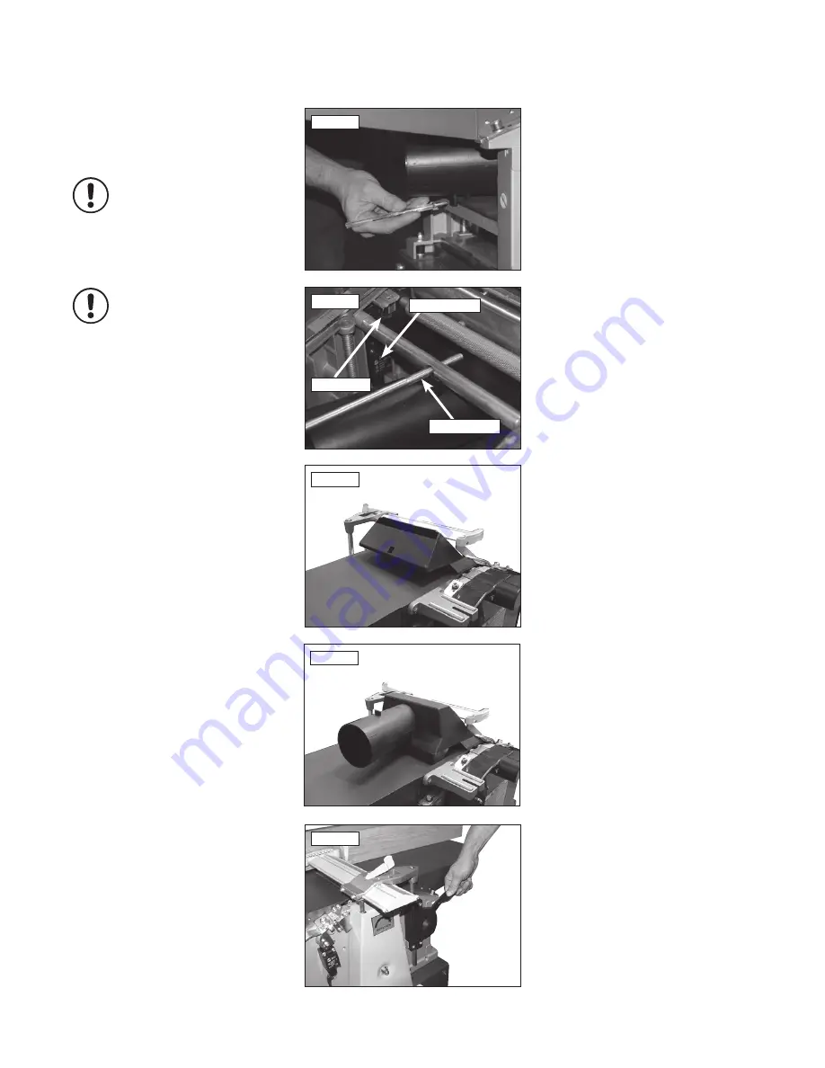
Set thicknessing bed to approximately 2/3
capacity and place extraction connector on to
it. Raise thicknessing bed to secure extraction
connector in position
Fig.6.1a
Note: The microswitch has to be
registered for the machine to operate
Fig.6.1b. Ensure that the notches in top
of the connector locks in the spacer shaft
& depth of cut adjusting bar.
Note: Adequate dust extraction must
be used with this machine - particularly
when processing large boards. Large
volumes of chips will be produced that
will clog the cutter block and extraction
chute having adverse effects on the
finish of you work. This could also lead
to damage of the machine that may
not be covered by the warranty if an
extractor is not used.
6.2 Chip removal when thicknessing
Thicknessing without dust collector: Take off the
outfeed table, slide cutter guard clear of table
and set guard to highest position. Swing chip
ejection hood over the cutterblock and secure in
place with the lock levers, as well as lowering
the guard on to it
Fig.6.2
.
Thicknessing with a dust collector:
Bring chip ejection hood into position as shown,
then place the suction connector on to it
Fig.6.3
. Secure with lock levers and guard.
Note: The chip ejection hood acts as a
cutterblock guard when the machine is
set up for thicknessing. Never operate
machine without chip ejection hood in
place and properly secured.
6.3 Setting cutter guard
Height adjustment is made with the lever
mounted on the left hand side of the machine.
After lifting the lock lever the cutter guard can
be slid sideways to set,
Fig.6.4
.
6.6 Thicknessing
Set thicknessing bed to required thickness of
workpiece (but a maximum 5mm more than
actual thickness of the workpiece).
Start machine and place workpiece with planed
side facing down on to thicknessing bed and
slowly push forward until feed roller engages.
Fig.6.1a
Fig.6.2
Fig.6.3
Fig.6.4
Fig.6.1b
i
Kg
i
Kg
Microswitch
Spacer shaft
Connector
Summary of Contents for PT260
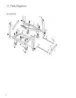
Page 28: ...28 11 Parts Diagrams Stand Wheel Kit ...
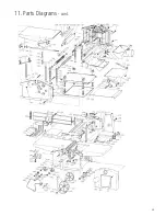
Page 29: ...29 11 Parts Diagrams cont ...
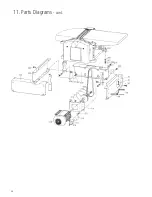
Page 30: ...30 11 Parts Diagrams cont ...
Page 34: ...34 ...
Page 35: ...35 ...


