background image

Your global partner for entrance solutions

Summary of Contents for DFA 70

Page 1: ...record DFA 70 User manual Your global partner for entrance solutions www record group ...

Page 2: ...Document identification Article nr 102 127109270 Version V1 0 Publication date 26 08 2022 Translation of the original manual Subject to technical modifications Copyright agtatec ag ...

Page 3: ... 15 3 3 Types of arm 15 3 4 Mechanical operating elements and displays 16 3 4 1 Mechanical BDI control toggle switch 17 3 4 2 Reset Button 17 3 4 3 Status indication 17 4 Specifications 18 4 1 Tecnical data 18 4 2 Door leaf weights and door widths 18 4 3 Instructions for low energy operators Low Energy 19 5 Operation 20 5 1 Controls of the STG 20 5 2 Electronic controller BDE D Option 21 5 2 1 Ope...

Page 4: ...irements for documentation 29 8 5 Operator duties 29 8 6 Spare parts and wearing parts 30 9 Taking out of service and disposal 31 9 1 Decommissioning 31 9 2 Dismantling and disposal 31 10 Drawings 32 10 1 Standard arm 32 10 2 Sliding arm Pull 32 10 3 Sliding arm Push 33 ...

Page 5: ...ardous situation that could lead to electric shock and cause serious injury or death 1 2 Intended purpose of use The system is designed exclusively for use as a pedestrian passage The installation must only occur in dry areas If there are deviations then proper waterproofing and water drains will be required on site Any other application or use beyond this purpose is not considered to be an intend...

Page 6: ...of the sensors NOTICE The installation must be inspected during the function and safety check for imbalance and signs of wear or damage to cables springs and fastening parts The equipment must NOT be used if repair or adjustment work needs to be carried out NOTICE Checking repairs service maintenance and cleaning may only be carried out when the system is at a standstill and switched off Before wo...

Page 7: ...ter the detection range of the sensors ð Do not make any settings on the control unit when the system is in use ð Have faults rectified immediately by specialist or personnel qualified to do so ð Remove objects from the opening area ð Do not disassemble put out of operation or manipulate safety devices ð Do not rush through a closing system CAUTION Risk of bruising and severing of limbs a If the s...

Page 8: ...ork on the electrical system performed by qualified personnel only DANGER Danger to life due to non functioning safety devices of the fire protection system a If safety devices of the fire protection system do not function properly there is a risk of serious or fatal injuries ð Never disconnect the fire protection system from the power supply overnight ð Do not disassemble put out of operation or ...

Page 9: ...istance of the shoes ensures that pointy objects do not penetrate the foot The high visibility vest is used to make the personnel stand out and therefore to be seen With improved visibility and attention the high visibility vest protects personnel in busy work areas from collisions with vehicles Depending on the place of work and the working environment the protective equipment varies and must be ...

Page 10: ...manual can be handed over in extracts to instructed personnel who are familiar with the operation of the system The illustrations are for basic understanding and may differ from the actual presentation Specific representations are contained in the drawings 2 2 Copyright The copyright for these instructions remains with agtatec ag The instructions may not be reproduced distributed or used for the p...

Page 11: ...ich can cause serious injuries and considerable damage to property a All work must be carried out by qualified personnel only b Keep unqualified personnel away from danger areas This operating manual is intended for the target groups listed below Operating entity of the system the person who is responsible for the technical maintenance of this system Operator of the system the person who operates ...

Page 12: ...evaluates the current door position the door speed and the final position at every instant and precisely calculates the optimum motion This makes the familiar end stops jerky braking actions creep speeds etc unnecessary Depending on the door width the corresponding spring range must be selected in the range of EN 4 to EN 6 according to European standard EN 1154 Safety is also additionally increase...

Page 13: ...lectronic BDE D Arm types Power transmission to the door leaf by use of standard arm pushing or sliding arm pulling pushing Locking optional Possibility on site to connect an electrical door opener 24 VDC Sensors Aesthetic actuating and self monitoring safety elements with adjustable sensitivity ensure optimum smooth and reliable operation of the door system 3 2 2 Setup 1 2 3 4 5 6 7 8 10 9 11 1 1...

Page 14: ...M4x8 4 1 102 031102 Quicklock BN833 SW 3 5 2 102 108691 Thread forming screw Pozidriv flat head DIN7500M SW VP M4x12 6 1 102 127125881 Insert part DFA 70 7 2 102 127126172 Cable guide bracket DFA 70 8 4 102 110755 ZK Schr I 6kt BN3873 VP M6x10 9 4 102 080029 Hex socket head cap screws fully threaded DIN912 VP M6x20 See Pos 11 102 127810198 Control unit STG 127 102 127808229_PCB assembled DFA 127 M...

Page 15: ...act Swing doors that are equipped with a monitored safety sensor in the opening direction SIO open after a collision at the programmed opening speed and not with a creep speed Reversing If the door hits an obstacle when closing a reopening is initiated immediately reversing The obstacle position is saved in the door operator and this position is approached gently the next time the door is closed O...

Page 16: ...elements and displays 1 Mechanical BDI toggle switch with three selectable operating modes 2 Reset button 3 Status display 4 Connection for service and configuration tools 5 Mounting kit BDI M If a mechanical control unit BDE M or an external control is used the toggle switch BDI must be replaced with the option BDI M 1 2 3 4 5 ...

Page 17: ...porarily adopted as the permanently open position fault 9 Open unsuccessful is displayed The mechanical BDI is always active ex works If an electronic BDE D is also connected the operating mode is determined by the BDE with the operating mode in highest priority via a defined priority structure For the operating mode the priority and code of the following table apply where BDE1 S1 and BDE2 S2 repr...

Page 18: ...econds 40 steps Closing speed Adjustable from 5 to 20 seconds 40 steps Noise level 45 dB Protection class IP20 Temperature range From 15 to 50 C Humidity range Up to 85 rel humidity not condensing 4 2 Door leaf weights and door widths Weight of door leaf kg Door leaf width m Recommended door leaf width for door closer size according to 600 0 100 200 300 400 500 0 6 0 7 0 8 0 9 1 0 1 1 1 2 1 3 1 4 ...

Page 19: ...erator breakdown with a manual pressure of max 67 N to release a locking device of max 90 N to set the door in motion or of max 67 N to open the door wide The force must be exerted on the main closing edge of the door and must be measured vertically to the main closing edge in the movement direction NOTICE The forces must be tested with appropriate force measuring device e g tension spring balance...

Page 20: ...N line termination J14 Primary Secondary Jumper in position M1 for Primary default setting Jumper in position S1 for Secondary Light emitting diodes LD1 red Control LED for button operation S1 LD2 green 35V Lights up if 35 V present from NET Dark if power failure has occurred LD3 green 24V Lights up if 24 V is present Caution If there is a power failure the processor reset occurs 1 second after th...

Page 21: ... 5 2 1 Operating modes and behaviour of the door during input signals Table of signals X marks a release reaction Explanation of the abbreviations see chapter Abbreviations Automatic AUTO Normal operation The door opens and closes automatically either by triggering of an activation device or by pushing the door if the touch control push to active is active CLOSED OPENING OPEN CLOSING AKI X X X X A...

Page 22: ...EN CLOSING AKI X X X AKA X X X SSK X X X X SIO X X X SIS X X TIPP OFF This operation mode can be used only in the USA The operator is switched to manual operation without configurations An SSK opening is possible but only under surveillance because some monitoring functions are disabled Functions like parameter settings Flash update continue to work CLOSED OPENING OPEN CLOSING AKI AKA SSK X X X X ...

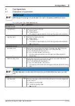
Page 23: ...ng the door remains minimally open after it has been opened by a trigger signal of type AKA AKI or tap automatic 0 20 0 to 20 seconds increment 1 s 21 40 22 to 60 seconds increment 2 s The time delay open starts when all trigger and safety signals for closing stop SSK time delay open 5 Determines the minimum time the door remains open after it has been opened by a trigger signal of the type SSK 0 ...

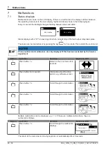
Page 24: ... only displayed if this has been activated by the Service department Button Operation Function Display on LCD E Press button 1 x Return to the main menu for 4 seconds Automatic E Press button for 2 seconds Information about the drive system e g software version E Press button 1 x Scroll through the information E Press button 1 x Scroll through the information Service Center Last malfunction 37 Mot...

Page 25: ...cted Check operation mode System operator Status LED flashing Restart controller and or control panel System operator Malfunction message on the display of the BDE D Restart controller and or control panel System operator Defective Close the door manually and notify a service engineer System operator Malfunction message still present after restart Malfunction could not be rectified Qualified perso...

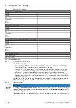
Page 26: ...ion book and a checklist These documents must be kept by the operator According to current legislation the operator of an automatic door system is responsible for its maintenance and safety With the care of the installation by the operator accidents or defects can be avoided Testing Type of test Action Visual inspection Check door leaves guides bearings limiting devices sensors and the securing of...

Page 27: ...t be performed by a competent service technician or an authorized partner Maintenance due is displayed on the BDE D operating unit if this function has been activated The interval for the output of this message is defined by the number of opening cycles and or after a certain operating time has elapsed Regular inspection and maintenance of the equipment by trained personnel authorized by the manuf...

Page 28: ...ulations accident prevention regulations directives and generally recognized technical regulations so they can judge the secure working condition of automatic door systems These people include for example technicians from the manufacturing or supplying company relevantly experienced trained personnel authorized by the manufacturer or other persons with appropriate expertise Experts must submit the...

Page 29: ...CE The installation must be inspected during the function and safety check for imbalance and signs of wear or damage to cables springs and fastening parts The equipment must NOT be used if repair or adjustment work needs to be carried out System operator tasks Task Personnel Time of implementation Entered in test log book Maintenance and cleaning of the sensors for safety and triggering System ope...

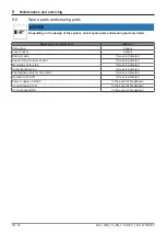
Page 30: ...lide shoe 3 years Lever socket 3 years Ball joint axle If wear is detected Support ring for lever socket If wear is detected Mounting set for stop If wear is detected Cable transmission If wear is detected Pushing flap only for fire doors If wear is detected Operator unit ATG If wear is detected Power supply unit NET In the event of breakdown Control device STG In the event of breakdown Control pa...

Page 31: ...be completely disassembled in reverse order The installation mainly consists of the following materials Aluminum Linking profiles Gearbox Drive panel Door wing profiles and side profiles Various profiles and small parts Steel iron parts Stainless steel casing Floor panel Box recess for floor installation Optional spacer or reinforcement profiles Gear components springs Various small parts like fit...

Page 32: ...10 Drawings 32 34 BAL_DFA_70_EN_1V0_REC_102 127109270 10 Drawings 10 1 Standard arm Hinge 10 2 Sliding arm Pull Hinge ...

Page 33: ...Drawings 10 BAL_DFA_70_EN_1V0_REC_102 127109270 33 34 10 3 Sliding arm Push Hinge ...

Page 34: ...Your global partner for entrance solutions ...

Reviews: