RecoveryPump
®
Model 737R (RPX)
User Manual
6. Components of the RecoveryPump
®
System
The RecoveryPump
®
Console
(See Figure 3 -
a)
The console takes air from the room environment, and sends it to the
individual air chambers in the garment in a sequence that starts from the
base of the garment and continues to the top, according to the selected
mode. The console then vents the air from the garments, there is a brief
pause, and the massage cycle repeats.
The RecoveryPump
®
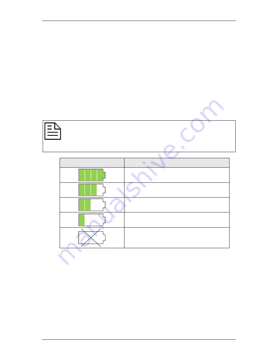
console is powered by either DC power adapter or by a
rechargeable battery pack inside the console. The battery pack can be
charged while the console is operated by electricity. The following table
illustrates the battery pack power capacity displayed by the status indicators.
Note:
•
Turn On the Main Switch to enable charging the console.
•
Turn Off the Main Switch to conserve battery power when not charging
or not using the console.
Battery Pack Status
Available Power
75% to 100% power
50% to 75% power remaining
25% to 50% power remaining
5% to 25% power remaining
Battery empty
Hose Bundle
The hose bundle transfers the air from the console to the garments.
The RecoveryCore™ garment is provided with two hose bundles. Each hose
bundle has a female connector that attaches to the connector on the garment,
and a prong connector that attaches to the console (see Figure 3 -
b).
The RecoveryBoots
®
and RecoveryArms
®
garments have built-in hose bundles.
L98005H1R-A
9


