GPIO SYNC
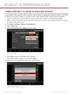
NOTE:
Using general purpose inputs/outputs and sync requires a DSMC2 expander. For more information, go to
"Input/Output Connectors" on page 205
.
SYNC
Use the Sync menu to set up genlock and Motion Control (MoCo). For more information, go to
Multi-Camera Setup" on page 162
.
NOTE:
Using sync and genlock requires a DSMC2 expander. For more information, go to
.
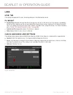
SENSOR SYNC MODE
Sensor Sync Mode allows the shutter timing (scan start) to sync to an external signal.
Off
: Sensor runs at the current recording frame rate. This is the default option.
Genlock
: Sensor synchronizes with the incoming compatible genlock signal.
MoCo
: Each rising edge on the sync input triggers a frame to be captured.
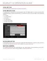
GENLOCK SOURCE
Select a genlock input:
BRAIN (Default)
Rear Module
BRAIN GPIO
NOTE:
Using general purpose inputs/outputs requires a DSMC2 expander. For more information, go to
.
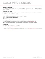
GPI Function (Camera Input)
: Select one (1) of the following options to configure the input for devices connected
to the SYNC connector on the camera:
Sync In
: The camera input is used as a sync-in signal for MoCo.
General Purpose In
: Use the BRAIN GPI In High/Low drop-down menus to map inputs to actions.
GPO Function (Camera Output)
: Select an options to configure the output for devices connected to the CTRL
connector on the camera:
Sync Out
: Provides an output sync signal to act as a shutter start tally.
Recording Indicator Out
: Provides a signal when recording is in process.
For more information, go to
"Input/Output Connectors" on page 205
.
GEN AND SYNC STATUS INDICATORS
The Lower Status Row of the camera display has GEN and SYNC indicators, which change color based on the current
genlock and sync statuses. For more information, go to
"System Status Indicators" on page 64
C O PYR I G HT © 2 0 1 6 R ED.C O M , I NC
9 5 5 - 0 1 3 3 _V 6 .3 , R EV - H
|
1 2 2
SCARLET-W OPERATION GUIDE

