955-0002_v3.3, Rev-B
COPYRIGHT © 2012 RED.cm, Inc.
63
63
RED BRICK
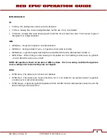
Attach to the camera using a V-Plate and 2B-to-1B Power Adapter Cable P/N 790-0138 to the DC IN
connector.
DC POWER
Connect a DC power source to the camera in one of the following ways:
•
Plug the RED AC Power Adapter into AC power, and the LEMO connector to the DC IN connector.
•
Plug the RED CHARGER into AC power, and the LEMO connector to the DC IN connector via 2B-to-
1B Power Adapter Cable P/N 790-0138.
•
Plug a 12V XLR based power source into the DC IN connector via adaptor cable P/N 790-0164.
NOTE: The maximum sustainable power load of the DSMC AC Power Adapter is 150W (15V@10A).
The output of the adapter is over current protected, and will shut down if an excess load condition
occurs. If the output trips for any reason, remove any external loads from the camera, such as
lights, motors etc, turn off the Adapter and repeat the above procedure.
POWER UP
Locate the camera’s Power ON / OFF button on the right face of the Brain. If the Power Status LED is
illuminated Red, depress and then release the Power / Record button. If not illuminated, check your
battery charge status or external power source cable connection. Once powered up the Power Status
LED will illuminate Green, confirming the camera is ready to use.
PREPARING TO RECORD
Before each days recording, the camera should be prepared as follows:
-
Physically set-up camera as desired.
-
Verify camera is using the latest firmware version at
upgrade the camera firmware. Refer to APPENDIX A: UPGRADING CAMERA FIRMWARE.
-
Insert a blank (or previously used but erasable) REDMAG 1.8” SSD and format it.
-
Perform a BLACK SHADING CALIBRATION of the Sensor.
-
Check your PROJECT SETTINGS (Time Base, Record Resolution, Record Quality, etc.).
-
Frame, focus and record.
CONNECT AND FORMAT MEDIA
Identify a REDMAG 1.8” 64GB, 128GB or 256GB SSD that has not previously been recorded to, or is not
a camera master and may therefore be erased and re-used. Aligned the RED logo of the SSD to the
outside, and then push the SSD firmly, but without excessive force, into the slot in the Side SSD Module.
Summary of Contents for EPIC-M
Page 1: ......
Page 244: ...955 0002_v3 3 Rev B COPYRIGHT 2012 RED cm Inc 243 243 Side View ...
Page 245: ...COPYRIGHT 2012 RED com Inc 955 0002_v3 3 Rev B 244 244 244 244 Top View Bottom View ...
Page 246: ...955 0002_v3 3 Rev B COPYRIGHT 2012 RED cm Inc 245 245 Back View ...
Page 247: ...COPYRIGHT 2012 RED com Inc 955 0002_v3 3 Rev B 246 246 246 246 APPENDIX M RESOLUTION CHART ...
Page 248: ...955 0002_v3 3 Rev B COPYRIGHT 2012 RED cm Inc 247 247 APPENDIX N MENU MAPS ...


