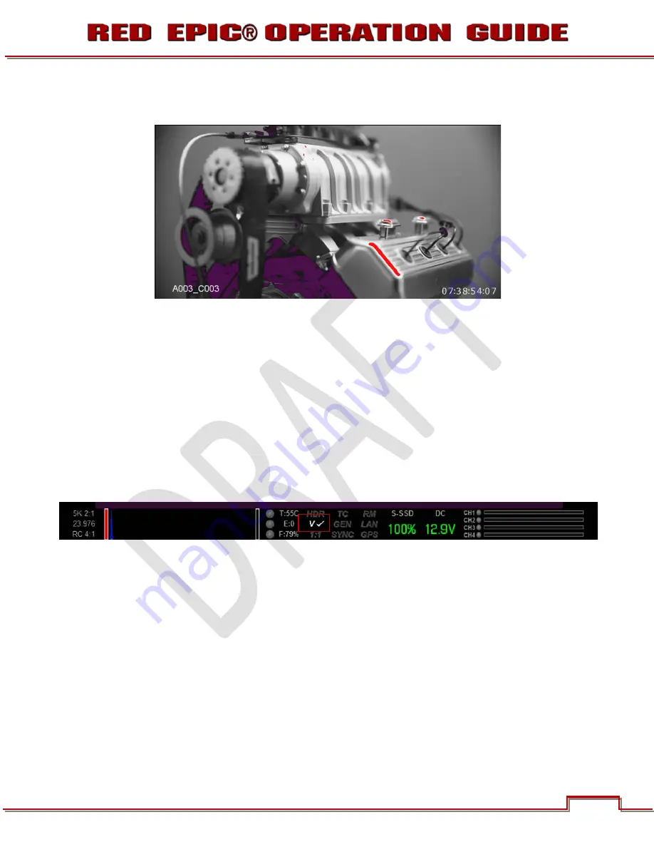
In the image, Purple areas represent sensor exposure levels that are likely to be noisy if gained up in
post production. Red areas represent sensor exposure levels that are at clipping.
NOTE: As EXPOSURE meters sensor RAW information, it is not affected by any RGB domain
adjustments - such as ISO rating, FLUT, White Balance, Video Gain or other LOOK information.
NOTE: Because the RAW data represents a wider color space than RGB, provided that the Red
(clip) color is not present in EXPOSURE view, even if Red (clip) color is present in VIDEO view, the
apparently clipped RGB highlights can be recovered in post production by adjustment of ISO,
FLUT or changing the KNEE and WHITE values of the CURVE box.
VIDEO
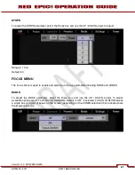
VIDEO displays a multi-color color overlay that allows you to check the video level of the RGB monitor
path (calibrated to the SMPTE test signal) and any outputs driven from that path - such as HD-SDI and
HDMI. When selected, the icon “V √” will be displayed n the Lower Status Group.
Purple represents Super-Black, Dark Blue represents Black, Teal represents 3-stops under 18% Gray,
Green represents 18% Gray, Pink represents Skin Tone, Straw represents White, and Yellow, Orange
and RED represent various degrees of signal clipping in RGB space.
By adjusting ISO, FLUT and Shadow while looking at VIDEO check, the operator can ensure that Black,
White and 18% Gray values conform to the desired levels on the HD-SDI and /or HDMI outputs.
Version 1.4.0 SVN 29352 BETA
73
APRIL 19, 2011
©2011 RED.COM INC.


