The backup LVS router performs the role of a standby system. Periodically, the LVS routers
exchange heartbeat messages through the primary external public interface and, in a failover
situation, the private interface. Should the backup LVS router fail to receive a heartbeat
message within an expected interval, it initiates a failover and assumes the role of the active
LVS router. During failover, the backup LVS router takes over the VIP addresses serviced by
the failed router using a technique known as ARP spoofing — where the backup LVS router
announces itself as the destination for IP packets addressed to the failed node. When the failed
node returns to active service, the backup LVS router assumes its backup role again.
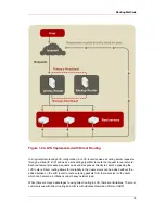
The simple, two-tier configuration in
Figure 1.21, “Two-Tier LVS Topology”
is suited best for
clusters serving data that does not change very frequently — such as static web pages —
because the individual real servers do not automatically synchronize data among themselves.
8.2. Three-Tier LVS Topology
Figure 1.22, “Three-Tier LVS Topology”
shows a typical three-tier LVS configuration. In the
example, the active LVS router routes the requests from the public network (Internet) to the
second tier — real servers. Each real server then accesses a shared data source of a Red Hat
cluster in the third tier over the private network.
Three-Tier LVS Topology
31
Summary of Contents for CLUSTER SUITE FOR ENTERPRISE LINUX 4.7
Page 4: ...Red Hat Cluster Suite Overview ...
Page 6: ...vi ...
Page 19: ...Figure 1 4 Power Fencing Example Fencing 9 ...
Page 21: ...Channel Connections Figure 1 6 Fencing a Node with Dual Power Supplies Fencing 11 ...
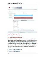
Page 34: ...Figure 1 17 Conga LVM Graphical User Interface Chapter 1 Red Hat Cluster Suite Overview 24 ...
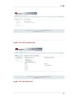
Page 49: ...Figure 1 25 luci homebase Tab Figure 1 26 luci cluster Tab Conga 39 ...
Page 76: ...66 ...
Page 78: ...68 ...


