5
TIME BASE SETTING PROCEDURE
The Apollo Time Base Rate Indicator has a time base selection range of
0.004 sec. to 32.764 sec. For a minimum time base (0.004 sec.), the X1 DIP
switch is set to “ON”. For the maximum time base, all the DIP switches would
be set to “ON” (these add up to 8191). Therefore, a specific time base is
achieved by adding up the appropriate individual time base increments.
The time base increment total is computed according to the following
formula:
TIME BASE INCREMENT = (Display Readout Desired) x DDP x (15,000)
TOTAL (TBIT)
[(Known RPM) x (Known PPR)] *
* -
Input Pulse Rate Per Minute.
DDP
: Use one of the following numbers in the above formula for the Display
Decimal Point (DDP) position.
0
= 1
0.0
= 10
0.00
= 100
DISPLAY READOUT DESIRED = 1800 (Direct Readout in RPM)
REVOLUTIONS PER MINUTE
= 1800
PULSES PER REVOLUTION
= 60
TBIT =
1,800
1,
×
80
1
0
×
×
1
6
5
0
,000
= 250
[
]
The appropriate Time Base switches, which together add up to 250, are then
set “ON”. Start by selecting the first increment which is greater than half the
desired TBIT, and add subsequent increments that are more than half the
difference needed.
TBIT = 250
DIP switch 8. . . . .
-
128
Needed =
122
DIP switch 7. . . . .
-
64
Needed =
58
DIP switch 6. . . . .
-
32
Needed =
26
DIP switch 5. . . . .
-
16
Needed =
10
DIP switch 4. . . . .
-
8
Needed =
2
DIP switch 2. . . . .
-
2
As shown above, DIP switches 2 and 4-8 are all set to “ON”. If it is desired
to know what the time is in seconds, multiply 250 x 0.004 sec. = 1 sec.
Note: This is the set-up for a one-second time base, which allows for direct
readout of RPM.
round to the nearest
whole number
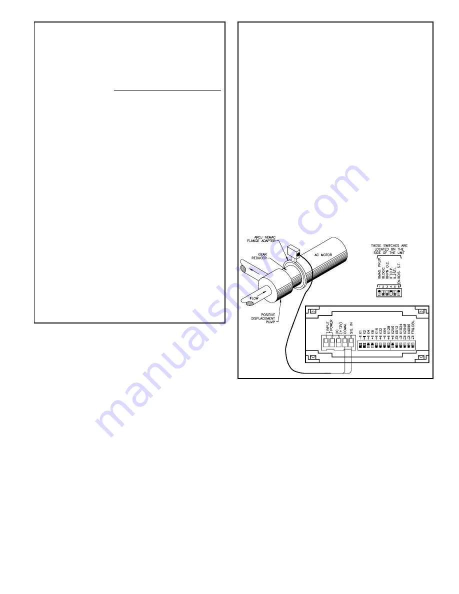
FLOW RATE INDICATION APPLICATION
A positive displacement pump is driven by a gear reducer and an AC motor.
An ARCJ NEMA C FLANGE is mounted to the end of this AC motor.
The magnetic pickup (which senses the gear) of the ARCJ adapter kit feeds
pulses to the APLR. The sensing gear, in combination with the pump and
reducer, provides 560 pulses for every gallon of fluid passing through the pump.
The Model APLR is used to read directly in tenths of gallons/min. in flow rates
up to 45 gallons/min. The following logical steps can be used to determine the
time base value required for direct readout. At 45 GPM, the number of output
pulses would be as follows:
45 gallons/min. x 560 pulses/gallon = 25,200 pulses/min.
Using the TBIT formula:
TBIT =
= 267.857
[
]
* -
For Tenths Position
** -
Input Pulse Rate Per Minute
TBIT = 268
DIP switch 9 . . . . . -
256
Needed =
12
DIP switch 4 . . . . . -
8
Needed =
4
DIP switch 3 . . . . . -
4
From the above calculation, DIP switches 3, 4, and 9, would be set to the
“ON” position. The tenths position decimal point must also be set to “ON”. So
the display will show 45.0 when 45 gallons are passing through the pump every
minute.
round to the nearest
whole number
(45) x (10)* x 15,000
25,200**


