2
1.
POWER REQUIREMENTS
: +24 VDC ±20% @ 30 W maximum.
Must use a Class 2 circuit according to National Electrical Code (NEC),
NFPA-70 or Canadian Electrical Code (CEC), Part I, C22.1 or a Limited
Power Supply (LPS) according to IEC 60950-1 or Limited-energy circuit
according to IEC 61010-1.
Power connection via removable three position terminal block.
Note:
1. The G310’s circuit common is not connected to the enclosure of the
unit. See “Connecting to Earth Ground” in the section “Installing and
Powering the G310.”
2.
BATTERY
: Lithium coin cell CR2025. Typical lifetime of 10 years.
3.
LCD MODULE
DISPLAYS
:
MODEL
G310C2
G310R2
G310S2
SIZE
10.4-inch
10.4-inch
10.4-inch
TYPE
TFT
TFT
TFT
COLORS
32K
32K
32K
PIXELS
640 X 480
800 X 600
640 X 480
BRIGHTNESS
450 cd/m
2
400 cd/m
2
1000 cd/m
2
BACKLIGHT LIFETIME * 50,000 HR typ. 70,000 HR typ. 50,000 HR typ.
BACKLIGHT TYPE
CCFL
LED
LED
*
Lifetime at room temperature. Refer to “Display” in the “Software/Unit
Operation” section.
4.
8-KEY KEYPAD
: for on-screen menus.
5.
TOUCHSCREEN
: Resistive analog
6.
MEMORY
:
On Board User Memory
: 32 Mbyte of onboard non-volatile Flash memory.
Memory Card
: CompactFlash Type II slot for Type I and Type II
CompactFlash cards.
7.
COMMUNICATIONS
:
USB Port
: Adheres to USB 2.0 specification full speed only via Type B
connection.
USB Host Ports
:
Comply with Universal Serial Bus Specification Rev 2.0.
Support data transfers at full-speed. Hardware over current protected (0.5
A max per port).
Serial Ports
: Ports are individually isolated. Format and Baud Rates for each
port are individually software programmable up to 115,200 baud.
PGM Port: RS232 port via RJ12.
COMMS Ports: RS422/485 port via RJ45, and RS232 port via RJ12.
DH485 TXEN: Transmit enable; open collector, V
OH
= 15 VDC,
V
OL
= 0.5 V @ 25 mA max.
Note: For additional information on the communications or signal
common and connections to earth ground please see the “Connecting to
Earth Ground” in the section “Installing and Powering the G310.”
Ethernet Ports
: 10 BASE-T / 100 BASE-TX
RJ45 jack is wired as a NIC (Network Interface Card). The jack shield is
electrically connected to Earth ground.
A secondary ethernet port (with its own Mac ID) is available as an option.
8.
ENVIRONMENTAL CONDITIONS
:
Operating Temperature Range
: 0 to 50°C
Storage Temperature Range
: -20 to 70°C
Operating and Storage Humidity
: 80% maximum relative humidity (non-
condensing) from 0 to 50°C.
Vibration according to IEC 68-2-6
: Operational 5 to 150 Hz, in X, Y, Z
direction for 1.5 hours, 2 g.
Shock according to IEC 68-2-27
: Operational 35 g, 11 msec in 3 directions.
Altitude
: Up to 2000 meters.
9.
CERTIFICATIONS AND COMPLIANCES
:
SAFETY
UL Listed, File #E245515, UL61010-1, ANSI/ISA 12.12.01-2007, CAN/CSA
C22.2 No. 61010.1, CSA C22.2 No. 213-M1987 and File #E179259,
UL61010-1, CAN/CSA C22.2 No.61010-1
LISTED by Und. Lab. Inc. to U.S. and Canadian safety standards
Type 4X Enclosure rating (Face only), UL50
IECEE CB Scheme Test Report #E179259-A1-CB-3
Issued by Underwriters Laboratories Inc.
IEC 61010-1, EN 61010-1: Safety requirements for electrical equipment
for measurement, control, and laboratory use, Part 1.
IP66 Enclosure rating (Face only), IEC 529
ELECTROMAGNETIC COMPATIBILITY
Emissions and Immunity to EN 61326: 2006: Electrical Equipment for
Measurement, Control and Laboratory use.
Immunity to Industrial Locations:
Electrostatic discharge
EN 61000-4-2 Criterion A
4kV contact discharge
8kV air discharge
Electromagnetic RF fields
EN 61000-4-3 Criterion A
10V/m (80 MHz to 1 GHz)
3 V/m (1.4 GHz to 2 GHz)
1 V/m (2 GHz to 2.7 GHz)
Fast transients (burst)
EN 61000-4-4
power
I/O signal
Criterion B
2kV
1kV
Surge
EN 61000-4-5 Criterion B
power 1 kV L to L, 2 kV L to G
signal 1 kV
RF conducted interference EN 61000-4-6 Criterion A
3 Vrms
Power freq. magnetic field EN 61000-4-8 Criterion A
30 A/m
Emissions:
Emissions
EN55011
Class A
Notes:
1. Criterion A: Normal operation within specified limits.
2. Criterion B: Temporary loss of performance from which the unit self-
recovers.
10.
CONNECTIONS
: Compression cage-clamp terminal block.
Wire Gage: 12-30 AWG copper wire
Torque: 5-7 inch-pounds (56-79 N-cm)
11.
CONSTRUCTION
: Steel rear metal enclosure with NEMA 4X/IP66
aluminum front plate when correctly fitted with the gasket provided.
Installation Category II, Pollution Degree 2.
12.
MOUNTING REQUIREMENTS
: Maximum panel thickness is 0.25" (6.3
mm). For NEMA 4X/IP66 sealing, a steel panel with a minimum thickness of
0.125" (3.17 mm) is recommended.
Maximum Mounting Stud Torque
: 17 inch-pounds (1.92 N-m)
13.
WEIGHT
: 5.44 lbs (2.47 Kg)
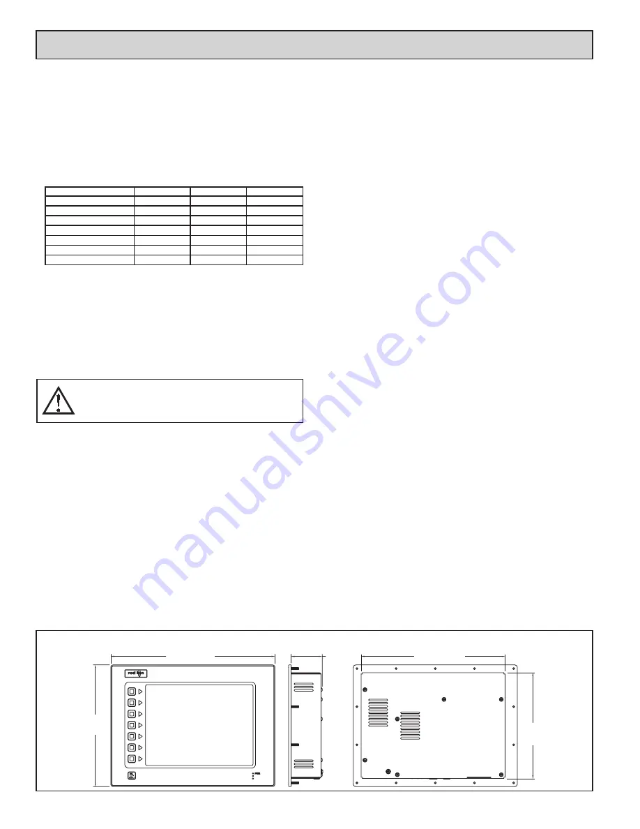
9.50
(241.3)
12.83 (325.8)
2.45 (62)
11.25 (285.8)
8.25
(209.4)
DIMENSIONS In inches (mm)
S
pecificationS
WARNING - DO NOT CONNECT OR DISCONNECT CABLES
WHILE POWER IS APPLIED UNLESS AREA IS KNOWN TO BE
NON-HAZARDOUS. USB PORT IS FOR SYSTEM SET-UP AND
DIAGNOSTICS AND IS NOT INTENDED FOR PERMANENT
CONNECTION.


