Wired Router Hardware & Installation Guide
7
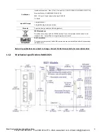
1.1.3
Router
View
1.1.4
Power
Specifications
and
Consumption
Power
is
supplied
to
the
router
via:
•
4
‐
pin
screw
terminal
•
Side
mounted
DC
2.5
mm
barrel
connector
router
4
‐
pin
Screw
Terminal
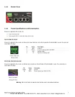
Power
is
supplied
to
the
router
via
the
4
‐
pin
Screw
Terminal
on
the
front
panel
for
the
RAM
‐
6021
router.
The
pins
are
described
as
follows:
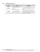
DC
2.5mm
Barrel
Connector
Power
is
supplied
to
the
router
via
the
barrel
connector
on
the
left
side
of
the
RAM
‐
6021
router.
The
contacts
are
described
as
follows:
Warning:
DC
2.5mm
barrel
connector
shall
not
be
used
in
hazardous
locations.
Power
connector
(facing
front)
Pin
Name
Description
1
GND
Ground
2
PWR+
Power
supply
input
(8
to
30
VDC)
3
OUT
Digital
output
4
IN
Digital
and
analog
input
Power
connector
(facing
left
side)
Pin
Name
Description
Sleeve
GND
Ground
Tip
PWR+
Power
supply
input
(8
to
30
VDC)
Phone: 800.894.0412 - Fax: 888.723.4773 - Web: www.clrwtr.com - Email: info@clrwtr.com


