


Services Tab
Revised 2017-08-31
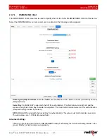
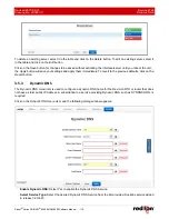
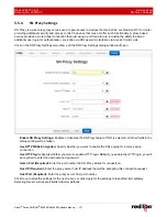
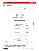
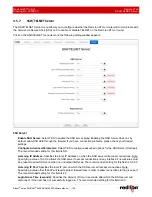
Dynamic DNS
Drawing No. LP0997-C
- 120 -
Sixnet
®
Series SN/RAM
®
6000 & RAM 9000 Software Manual
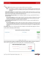
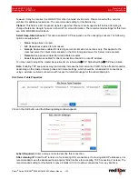
Enter User Name (Required):
Enter the User Name used to access your Dynamic DNS Service in this field.
Enter Password (Required):
Enter the password used to access your Dynamic DNS Service in this field.
Confirm Password (Required):
Re-enter the password entered in the field above. The password must match
exactly.
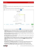
Select Interface:
Specify the interface you want to access via Dynamic DNS. Changes made to the interface
configuration after enabling Dynamic DNS will result in updates being sent to your Dynamic DNS service
provider.
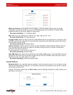
Host Name (Required):
Enter the host name and domain you which to be assigned by the Dynamic DNS
Service.
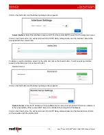
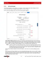
Server Name/Address (Required):
Enter the host name or IP Address (along with port number, if needed) for
user to access the Dynamic DNS Server.
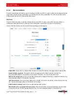
Example:
members. dyndns.com:80
The recommended setting for this field is automatically displayed when you select a Service Provider. If you
require a value other than the recommended value, your Network Administrator or Dynamic DNS Service
Provider should be able to provide the appropriate value, which can be entered manually.
Server Request Path (Required):
Enter the Request URL required to connect to the Dynamic DNS Service in
this field.
The recommended setting for this field is automatically provided when a Service type is selected. If you require
a value other than the recommended value, your Network Administrator or Dynamic DNS Service Provider
should be able to provide the appropriate value, which can be entered manually.
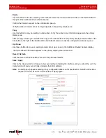
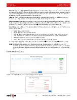
Click on the
Save
button for changes to be saved without activating the interface until you reboot the unit, the
Apply
button will save your settings and apply them immediately. To revert to the previous defaults, click on the
Revert
button.


