INSTALLATION
Typical Installations
3
INSTALLATION
Typical Installations
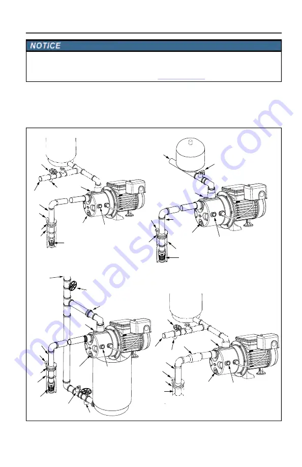
The following drawings illustrate how the system should be arranged in the plumbing system.
Risk of damage to pump or other equipment.
•
Periodically inspect pump and system components. Regularly check piping for weakness or wear, making certain that all connec
-
tions are secure.
•
Schedule and perform routine maintenance as required. Refer to
.
SHALLOW WELL - INLINE TANK (WITH FOOT VALVE)
SHALLOW WELL (WITH FOOT VALVE)
Pressure gauge port
(1/8" NPT)
Well
Well seal
Vent pipe
Suction pipe
Foot valve
Relief valve
Service line
Drain
Tank
Priming plug
Drain plug
Drain plug
Relief valve
Service line
Tank
Priming plug
Well
Well seal
Vent pipe
Suction pipe
Foot valve
Pressure gauge port (1/8" NPT)
Drain plug
Well
Well seal
Vent pipe
Suction pipe
Foot valve
Relief valve
Service line
Drain
Tank
Priming plug
Union coupling (2 required)
Pressure gauge port
(1/8" NPT)
SHALLOW WELL - TANK-MOUNTED SYSTEM (WITH FOOT VALVE)
Drain plug
Well
Well seal
Vent pipe
Suction pipe
Relief valve
Service line
Drain
Tank
Priming plug
Inline check valve
Pressure gauge port (1/8" NPT)
SHALLOW WELL (WITH INLINE CHECK VALVE)
Shutoff Valve
Summary of Contents for RJS-75SS Series
Page 31: ...31 NOTAS ...


