25
USER MANUAL
▪
Red Rooster Lifting Limited
▪
Nauta House, The Meadows, Oldmeldrum, Aberdeenshire, AB51 0EZ
▪
Tel: +44 (0) 1651 872101
▪
M01-AH13-ATLF REV1
TROLLEY VANE MOTOR MAINTENANCE
4.3
These motors are made to precise tolerances and it is vital for efficient operation to achieve minimum clearances throughout. Every clearance
represents an air leakage path from inlet to exhaust, which will detract from the starting and running characteristics.
The spacing of the rotor is of prime importance in two ways:
▪
Rotor to end covers (side clearance) (Cs) nominally 0.050mm (0.002").
▪
Rotor to body casing (top clearance) (Ct) nominally 0.050mm (0.002").
To achieve the side clearance each repair kit has a series of plastic shims, colour
coded to different thicknesses.
Purple = 0.025mm (0.001")
Blue = 0.050mm (0.002")
Green = 0.076mm (0.003")
Orange or Brown = 0.102mm (0.004")
This range of vane motors has two styles of rotor locations.
V4 rotor location by one double row bearing in rear cover.
V6 rotor location by one double row bearing in front cover.
ASSEMBLY DETAILS
All parts must be clean and it is recommended that new oil seals and blades
are fitted as a matter of course. Press all bearings fully home into their respective
covers, pressing only on the outer track to prevent damaging the bearings. On V4
motor fit oil seal retaining circlip and a new oil seal.
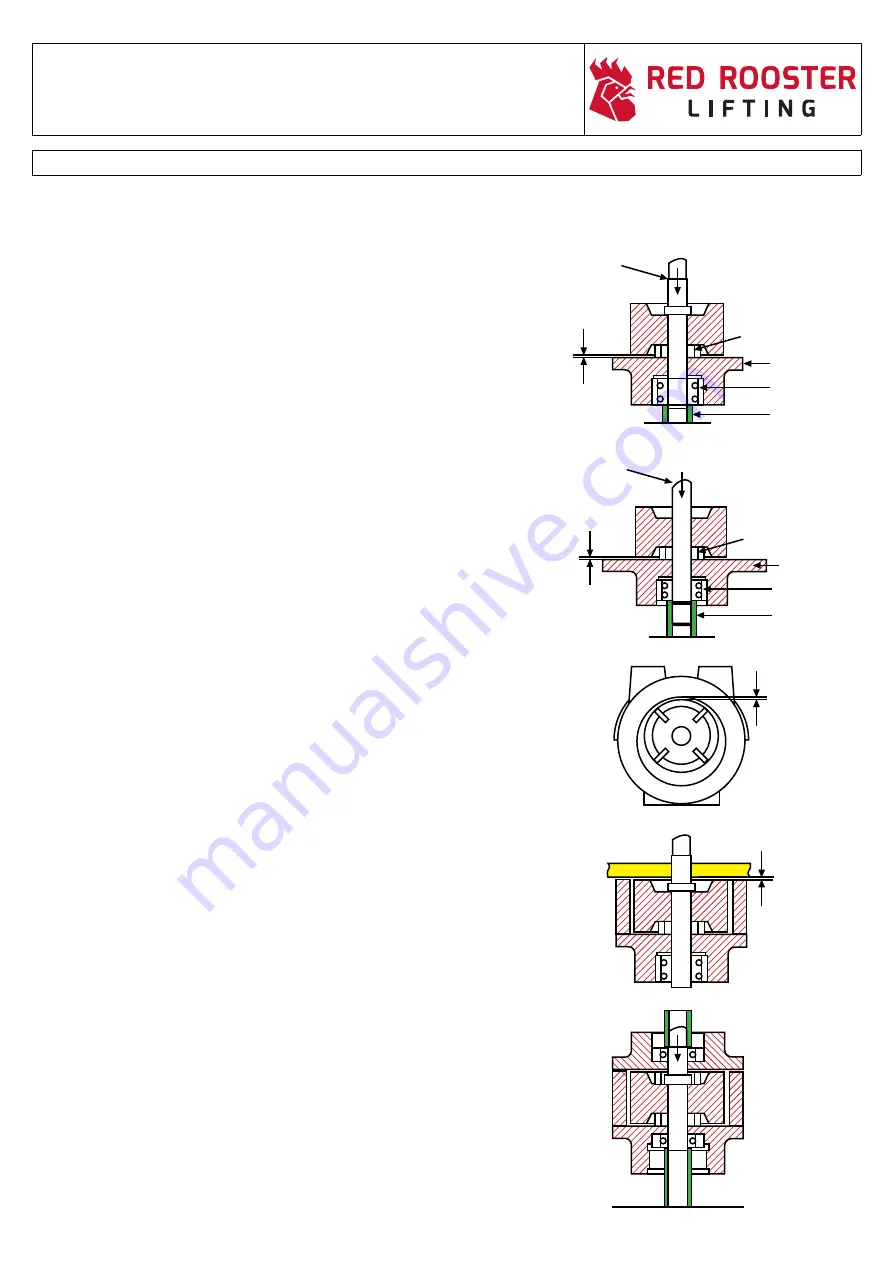
Take the location cover for your particular motor i.e. V4 rear cover and V6 front
cover.
Provide good support on the inner bearing track, as the shaft fit is very tight, to
provide rotor location. Place blade ejector ring central on cover and press
rotor/shaft assembly down until there is a clearance. Cs of 0.050mm (0.002")
between rotor and cover, check this clearance is even all round the rotor. Fit a
blue plastic body gasket cover, lowering the body into position over the rotor
assembly, locating on the existing dowels.
NOTE: Ensure the body is the correct way round i.e. port arrows towards the output shaft.
Tighten body bolts and check top clearance, Ct, see Fig. 4. This should be
0.050mm (0.002") if there is a problem with this then reposition and drill for new
dowels. Insert second ejection ring, fit new blades, it may be necessary to work
the lower ejection ring across in order to fit the opposite blade. Refer to Fig. 5
(axial and clearance, Cs). Measure this by putting a straight edge across the body,
then use the feeler gauges in the gap between rotor and body face. This should be
made up to 0.050mm (0.002") or as close as possible using the gasket set provided.
Ensuring it is free to rotate. On V4 and V6 motors the second cover should slide down
into position easily as the second bearing fit is non-locating.
On V6 motors the front oil seal is carried in a separate housing, this should be fitted
next, followed by the rear bearing cover and its gasket. On V4 motors the rear bearing
cover and its o-ring can now be fitted.
Ct
Fig. 4
Ct
Fig. 5
Fig. 6
Rotor / Shaft
Assy
Cs
Ejection ring
Rear cover
Bearing
Bearing Support
V4 Motor
Rotor / Shaft
Assy
Cs
Ejection ring
Bearing
Bearing Support
Front cover
V6 - V8 - V10 Motor
Summary of Contents for AT2S-LF
Page 1: ...LUBE FREE AIR HOIST TROLLEY USER MANUAL MODEL TCS 980 AT2S LF...
Page 2: ......
Page 44: ......
Page 60: ......


