background image

6

4-GUARANTEE

RED grants a five-year guarantee for Premium high performance flat plate solar collectors, according to the following guarantee terms.

1.  A system guarantee for the entire system of Premium high performance flat plate solar collectors is granted. The system comprises 

collectors, assembly accessories, connections and connection pipes (Solar Pipe), solar pump station, adjustment control unit ,safety 

devices.

2.  The five-year guarantee period starts when the system is delivered to the customer. The start date is the date shown on the delivery 

note.

3.  The conditions of the guarantee are that the system is installed according to the installation instructions supplied by RED and the 

specific regulations in force and that regular, periodic maintenance is carried out by qualified technical staff in line with the specifications 

contained in the instruction manual. Maintenance operations must be documented and proven to validate the guarantee The customer 

is responsible for paying maintenance costs. It must also be proven and documented that the entire system has been put into operation 

according to the details specified in the manuals.

4.  The guarantee does not cover:


a. 

natural wear;


b. 

excessive stresses and inappropriate treatment;


c. 

the use of inappropriate heat transfer fluids;


d. 

damage developing due to chemical and electrochemical agents;


e. 

damage due to incorrect storage of the system by the end customer;


f. 

corrosion damage caused by the formation of moisture inside collectors;


g. 

breakage of glass, except where the defect is caused by a manufacturing error or a defect in the material itself;


h. 

theft, natural disasters, etc.


i. 

the use of accessories or fluids not certified by the manufacturer;


j. 

electrical and mobile components (pump, regulator, valves, batteries, expansion vessels...);


k. 

transportation damage;

5.  The delivery note (together with the original paid invoice) constitutes proof of guarantee.

6.  The customer must immediately inform RED of any faults (a maximum of 14 days after detection of the fault).

7. 

The guarantee shall no longer be valid:


a. 

if faults are not communicated immediately;


b. 

if a modification not indicated in the instruction manual is made to the system;


c. 

if original parts are replaced without consulting RED;


d. 

if the checks specified in the manuals are not carried out;

8.  If there is a fault the customer must not put the system into operation. This is to prevent further damage. If this instruction is not 

observed and further damage is caused the guarantee shall not be valid.

9.  Supply and delivery terms are indicated in the General Conditions of Sale.

10.  If one of these conditions is not effective, the remaining regulations remain valid. The parts still imply that a non-effective regulation 

must be replaced with an effective regulation that meets the meanings and intentions of the subsequent non-effective condition.

COURT WITH JURISDICTION

In the event of any controversy, the court with jurisdiction is the Court of Pordenone (Italy).

DISPOSAL

Dispose of the product in compliance with the regulations in force in the relevant place, region or country.

Summary of Contents for HIGH PERFORMANCE SOLAR COLLECTOR

Page 1: ...HIGH PERFORMANCE SOLAR COLLECTOR USE AND INSTALLATION MANUAL EN Translation of original instructions ...

Page 2: ...RDS REGULATIONS GUIDELINES 5 4 GUARANTEE 6 5 TECHNICAL SPECIFICATIONS AND DIMENSIONS 8 6 MATERIALS FOR ROOF INSTALLATION 11 7 TYPE OF INSTALLATION 15 8 FILLINGWITH HEATTRANSFER FLUID 26 9 TECHNICAL DATA 29 10 MAINTENANCE CHECKS 30 11 RED SYSTEM FILLING STATION 31 12 PROBLEMS AND FAULT DIAGNOSIS 32 ...

Page 3: ...s or property damage resulting from failure to observe the instructions contained in the manuals supplied with the cylinder Before attempting to install collectors read and familiarise yourself with these safety warnings You are advised to check the static load if the installation location of the solar system is 600 metres above sea level and exposed to heavy snow The protective caps of the collec...

Page 4: ...tingcorrectly switchtheapplianceoffanddonotmakeanyattempttorepairitorserviceit directly Contactonlylegallyqualifiedstaff AnyrepairstoproductsmustbecarriedoutonlybystaffauthorisedbyRED usingonlyoriginal parts Failure to observe the above recommendations may compromise the safety of the appliance To guarantee the efficiency of the appliance ensure that it functions correctly it is vital that qualifi...

Page 5: ...y flammable materials e g petrol paints paper in the area where the applianceisinstalled TECHNICAL DATA LABEL Caution Thelabelispositionedonthesideofthecollector WORKING ON THE ROOF Always adopt appropriate safety measures The following instructions must always be followed for safe installation of the solar system always use anti fall protection when working on a roof Always observe safety regulat...

Page 6: ...o various degrees below zero caused by the particularly highperformanceofthecollector Thismayleadtothedestructionofthesolarsystem PACKAGING RED solar collectors are supplied fully assembled After removing the appliance from the packaging ensure that the product supplied is complete and undamaged The packaging elements straps plastic bags etc must be kept out of reach of children as they present po...

Page 7: ... components pre assembled systems part 1 general requirements PrEN 12976 2 solar thermal systems and their components pre assembled systems part 2 carrying out tests PrEN 12977 1 solar thermal systems and their components systems built according to customised design part 1 general requirements PrEN 12977 2 solar thermal systems and their components systems built according to customised design part...

Page 8: ...ed by the formation of moisture inside collectors g breakage of glass except where the defect is caused by a manufacturing error or a defect in the material itself h theft natural disasters etc i the use of accessories or fluids not certified by the manufacturer j electrical and mobile components pump regulator valves batteries expansion vessels k transportation damage 5 The delivery note together...

Page 9: ...guardo a violazioni di brevetti o di diritti di terzi riconducibili all impiego della presente prodotto Il produttore si riserva il diritto di apportare senza preavviso eventuali modifiche inerenti al prodotto ai dati tecnici o al manuale Nel caso in cui non fosse più possibile un funzionamento privo di pericoli p es per danni visibili disattivare immediatamente l apparecchio RICHIESTA DI INTERVEN...

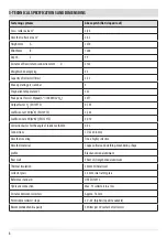
Page 10: ...1W m2 K EN 12975 3 543 Coefficient at2W m2 K2 EN 12975 0 010 Correction factor for the angle of incidence IAM50 0 93 Connections CU 22 x 0 8 mm Absorber covering Tinox highly selective Absorber material Copper ultrasound welding meandering shape profile Black anodised aluminium Rear wall Sheet of strengthened aluminium Thermal insulation 50 mm mineral wool Collector glass 3 2 mm solar safety glass...

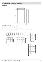
Page 11: ...sion test connections through parallel pipe connections These connection diagrams are purely a suggestion for installation and do not replace the technical design Technical Dept All rights reserved Reproduction is prohibited SINGLE ROW DOUBLE ROW DOUBLE ROW TRIPLE ROW TRIPLE ROW ...

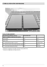
Page 12: ... mm 2270 Collector width mm 1260 A distance between roof hooks of 1 collector mm Approx 800 1060 B distancebetweentheroofhookandtheedgeofthecollector mm Min 100 C vertical distance between the roof hooks mm 2000 2200 Variable interval dependant on the width of the tiles and spacing of the beams Variable interval dependant on the height of the tiles C O L L E C T O R H E I G H T COLLECTOR WIDTH ...

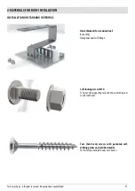
Page 13: ... Bolts M8 Hexagonal nuts with flange Self locking screws M10 Tofastenthesupportingrailsandtheassemblingrails to the roof hooks Torx 5x60 mm screws with patented self drilling points and certified model For fastening standard hooks onto beams Technical Dept All rights reserved Reproduction is prohibited ...

Page 14: ...rail upper and lower rails are made in the same way For upper and lower collector fastening The diagrams illustrate assembly on the roof beams You may need to use longer screws for wood to ensure stable fasteningbetweenthebeamandthehook Thisdependsontheconstructioncharacteristicsoftheroof Beforestartingtheinstallation checkthattheroofhasadequatesupportcapacity ...

Page 15: ...d certified model For hook fastening on flat tiles The diagrams illustrate assembly on the roof beams You may need to use longer screws for wood to ensure stable fasteningbetweenthebeamandthehook Thisdependsontheconstructioncharacteristicsoftheroof Beforestartingtheinstallation checkthattheroofhasadequatesupportcapacity Technical Dept All rights reserved Reproduction is prohibited ...

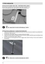
Page 16: ...ERIALS FOR ROOF INSTALLATION INSTALLATION ON SPECIAL COVERING SCREW HOOKS Flanged hexagonal nut M12 Supporting rail support Flanged hexagonal nut M12 Flanged hexagonal nut M12 Seal Screw hook Special accessory ...

Page 17: ...ar to be problems with the support surfaces 2 Ensure that the roof hook is approximately 2 3 mm away from the tile It may be necessary to add a piece of wood to some tiles to act as a spacer Now tighten the roof hook firmly onto the support plate using a 13 mm flat wrench or a ring spanner 3 Grind as much material as necessary from the tile using an angle grinder so that the roof hook is perfectly...

Page 18: ... intervals according to the dimensions of the collector Drill along a straight line using a lead plumb line Only drill using a stable substructure 2 Pre drill using a 10 mm bit beam then use a 16 mm bit for the tiles roof covering 3 Tighten the screw hook onto the pre drilled beam via the tiles Fasten the seal together with the hexagonal nut with flange Adjust the distance of the supporting rail s...

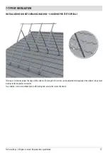
Page 19: ...ection to adjust the slope of the collector The length of U sections can be adjusted telescopically if the collector slope must be adjusted to be greater or smaller Two stainless steel screws M8x50 and self locking nuts are used to secure the device Technical Dept All rights reserved Reproduction is prohibited ...

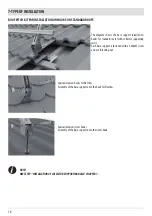
Page 20: ...ard roofs with collector supporting rails Each base support is fastened with an M8x55 screw and a self locking nut Special solution hooks for flat tiles Assembly of the base support onto the hook for flat tiles Special solution screw hooks Assembly of the base support onto the screw hook NOTE NEXTSTEP INSTALLATIONOFCOLLECTORSUPPORTINGRAILS CHAPTER7 ...

Page 21: ...F KIT Intervals A Approx 800 1070 mm Depth B 1650 mm Telescopic height C Extendable to an inclination of approx 60 Calculation of the distance between the rows of collectors to prevent reciprocal shading E g Angle of elevation of the sun 17 at 21 12 Germany Collector inclination a min 34 45 60 Distance b 6 05 6 85 7 55 Weight relative to wind load kg m2 collector surface in accordance with DIN 105...

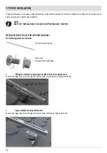
Page 22: ...GRAILS CHAPTER7 INSTALLATION OF COLLECTOR SUPPORTING RAILS The following parts are required Collector supporting rail M10 screw Hexagonal nut with flange 1 Fitting the collector supporting rail onto hooks for standard roofs Position the supporting rail on the upper and lower hooks for standard roofs Tighten the bolts 2 Special solution hooks for flat tiles Position the supporting rail on the upper...

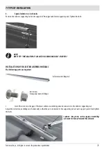
Page 23: ...g parts are required Collector assembling rail M10 screw Hexagonal nut with flange 1 Insert the screw into the gap of the lower collector assembling rail and connect it to the collector supporting rail Adjust the collector assembling rails horizontally so that they are connected to the supporting rails at each support point Next tighten the bolts Caution the groove on the upper assembling railmust...

Page 24: ...roove on the upper assembling rail must be turned towards the collector 3 The collector assembling rails can be connected for extension with the rails connector included in the supply NOTE NEXTSTEP ASSEMBLYANDINSTALLATIONOFCOLLECTORS SEECHAPTER7 ASSEMBLY AND INSTALLATION OF COLLECTORS The following parts are required Solar collectors ...

Page 25: ... Slot the upper assembling rail into the collector gap with a click The upper assembling rail is fastened with the screws after connecting the collectors 3 An o ring must be fitted on each end of the connection joint Forgetting to fit the o ring will cause the system to leak Technical Dept All rights reserved Reproduction is prohibited ...

Page 26: ...y the two ends are fastened to each other and the o ring is fastened and held down Check that the collectors are assembled so that they are absolutely solid and safe and that the connections are tightenedcorrectlytoeachother NOTE NEXTSTEP CONNECTIONOFCOLLECTORS SEECHAPTER7 CONNECTION OF COLLECTORS The following parts are required Connection plus kit Cap plus Before assembling the cap the o ring mu...

Page 27: ...embling the collector the o ring must be assembled Fully insert the sensor into the flow line connection and tighten the union nut Protective pipe with heat shrink tube on the flow connection Technical Dept All rights reserved Reproduction is prohibited ...

Page 28: ...sed to use a 50 50 mixture ratio It is essential to mix the heat transfer fluid in a separate tank before filling the system Collectorsmustbefilledwithheattransferfluideveniftheexternaltemperatureoftheplanishigherthanfreezing 0 C MIXING THE HEAT TRANSFER FLUID L SOLARPIPE FILLING AND DISCHARGE VALVES HEAT TRANSFER FLUID TANK CONNECT THE FILLING STATION FOR RINSING FILLING THE SOLAR SYSTEM HERE EXP...

Page 29: ...lectors can never be fully emptied afterwards vapour and ice may cause damage Collectors must therefore be rinsed with the glycol mixture Only RED solar heat transfer fluid must be used on our collectors Table of heat transfer fluid mixture ratios Propylene glycol water Density at 20 C g cm3 Frost protection C Viscosity 20 C mm2 s 25 75 1023 10 2 7 30 70 1028 15 3 9 35 65 1031 18 4 1 40 60 1038 24...

Page 30: ...h integrated adjustment valve indications in l min Adjust the calculated flow with a hexagonal allen wrench while the pump is operating clockwise rotation reduces the flow See solar pump station manual ELECTRICAL CONNECTIONS Electrical devices must be installed by qualified staff according to the standards in force and the specifications of the local competent authorities ...

Page 31: ...welding according to DIN 8513 Pressurised THERMAL INSULATION OF PIPES Insulation used for pipes must have the following characteristics stability at temperatures above 150 for short periods of time e g fibreglass India rubber External parts must be resistant to UV rays and other atmospheric agents e g metal leaf casing Insulation thickness diameter of the pipe minimum based on a coefficient K of 0...

Page 32: ... the system Also rinse and clean the system using the filling station Check the seal of all connections and the tightness of the screws on the assembly parts Visually check the collectors for any damage Check the pressure in the expansion vessel and all of the safety devices Check the operation of the connected tank and its safety devices Get qualified staff to check all the hydraulic electrical a...

Page 33: ...maintenance of closed circulation systems such as solar underfloor and heating systems To save money during system washing bleeding and filling operations robust high output pump with on and off switches protected by water sprays Stainless steel pump canister Filling and return pipes are resistant to high pressures and are transparent to aid visual checks Shut off ballcock on the bottom of the tan...

Page 34: ... The pump is working bit the flow and return sections are at the same temperature The pump is very hot There is air in the system The valves are closed Check the pressure of the system Bleed the system fully using the solar filling station Open the valves The cylinder cools down during the night the flow and return sections are at different temperatures after the pump is switched off during the ni...

Page 35: ......
Page 36: ...tanafredda PN ITALY Telephone 0434 599599 r a Fax 0434 599598 Internet www mcz it e mail mcz mcz it For further technical information regarding installation or operation please contact the TECHNICAL ASSISTANCE AFTER SALES DEPARTMENT Monday to Friday 8 00 to 12 00 and 14 00 to 18 00 ...

Reviews: