6
1
PRODUCT FUNCTION
1.3.3 Optional External LED
An option external LED (see Figures 2.7.1 and 2.7.2) can be used to provide charge status and error
feedback away from the BCDC unit and is voltage limited to 9 V and current limited to 6 mA. A serial
resistor and LED should be selected to these specifications. A basic 3 V LED can be wired as shown.
If used, this external LED is either OFF (BCDC not charging), ON (BCDC charging) or FLASHING (see error
codes in Section 1.5 Error Codes). A “12 V” LED (3 V with integrated resistor) will not operate correctly if
installed.
1.3.4 Charging Process
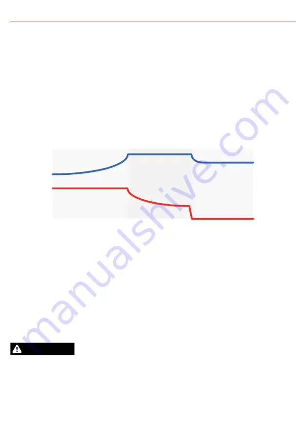
Voltage
Float
Absorption
Boost
Current
Charging Process
FIGURE 1.3.4.1:
Charging Process
When the Charger is turned on, it will move into the Boost stage. The Boost stage maintains a constant
current until the battery voltage reaches its Absorption Voltage. The current in Boost stage may vary
during operation in order to maintain safe operating temperature, or to limit the difference between input
and output voltages.
The Charger will then move to Absorption stage which maintains a constant voltage level for a
predetermined period of time or until the current being drawn by the output battery drops to less than 4 A
for 30 seconds; after which the Charger will enter Float stage.
Float stage maintains 13.3 V (13.6 V for LiFePO
4
) on the output battery, keeping the battery topped up.
This counteracts the battery’s self discharging or loads applied to the battery. When the battery loses
charge, the Charger will move back into the Boost stage.
CAUTION
When using the Battery Charger to charge a Lithium Iron Phosphate battery, only batteries that feature an
inbuilt battery management system featuring inbuilt under and over voltage protection and cell balancing
are suitable.


