12 | Installation
3.2 Installation Overview
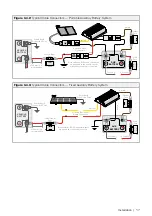
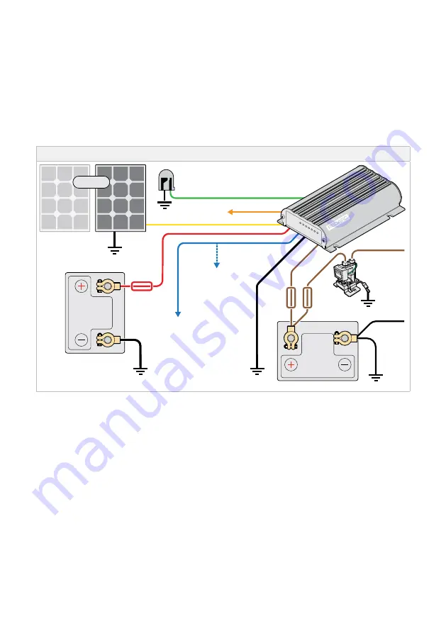
"Figure 3.2.1.1: Typical Battery Setup"
provides a generic overview of the BCDC Core's interfaces
with the components recommended to charge an auxiliary battery. Refer to
to plan the required cabling, fusing and connections needed for your installation.
REDARC recommends that the Battery Charger be installed by a suitably qualified person.
3.2.1 BATTERY SETUP
Figure 3.2.1.1:
Typical Battery Setup
12 V
Standard Trigger
Settings
Leave unconnected
or connect to Ground
Optional
LED
Refer to Charging
Profile Select
GREEN
ORANGE
Connect all ground
points to chassis earth
Auxiliary
Battery
Fuse*
1
BLACK
BROWN
Load
Fuse
Loads
Low Voltage
Disconnect
(optional)*
4
12 V or 24 V
Start Battery
Bank
12V Solar Panel Array
(Unregulated)*
3
Low Voltage
Trigger Settings
to D+ or Vehicle
Ignition*
2
YELLOW
RED
BLUE
Fuse*
*
1
Fuse Ratings to be as per the table in
"Table 3.5.1: Fuse Rating" (page 18)
.
*
2
To connect the Blue wire to the vehicle's ignition, connect the Blue wire to an ignition switched fuse in one
of the vehicles fuse boxes, located in either the engine compartment or vehicle cabin.
*
3
Do not connect regulated solar panels. If solar is not connected, tape over unused wires.
*
4
The SBI-12LLD Low Voltage Disconnect is an optional component used to protect the auxiliary damage from
excessive discharge.
Summary of Contents for BCDCN1225
Page 34: ...34 NOTES ...
Page 35: ...35 ...


