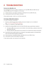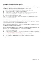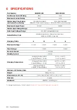
22 | Installation
3.7.5 VEHICLE IGNITION INPUT — BLUE WIRE
The
BLUE
wire is required for the BCDC Core to operate in Low Voltage mode when installed in
vehicles with variable-voltage alternators.
If required to leave the
BLUE
wire disconnected, apply electrical tape over the end of the wire.
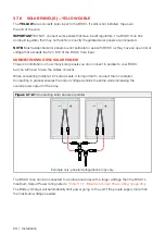
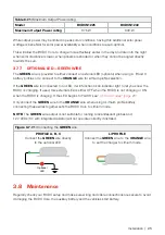
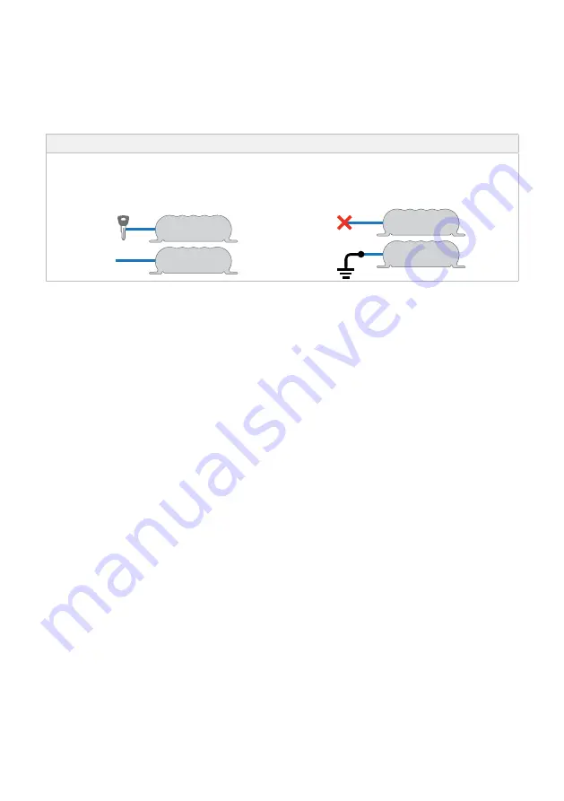
Figure 3.7.5.1:
Connecting the
BLUE
wire
LOW VOLTAGE MODE
Connect the
BLUE
wire to IGN for continuous
Idle vehicles, or to D+ for Idle-stop vehicles.
STANDARD VOLTAGE MODE
Leave the
BLUE
wire disconnected,
or connect to Ground.
Vehicle
Ignition
D+
LOW VOLTAGE MODE
Modern vehicle electrical systems use variable voltage alternators that output a wider range of
voltages. To improve auxiliary battery charging, the BCDC incorporates a ‘Low Voltage Mode’
which increases the voltage range the auxiliary battery charging takes place. To enable this mode,
connect the
BLUE
wire to a signal which is active when the engine is running. For most vehicles
the 'Ignition ON' signal is sufficient. A suitable signal source is commonly found in the vehicle's
engine bay or cabin fuse box.
For vehicles equipped with ‘Idle-Stop’ or ‘Stop-Start’, connect the
BLUE
wire to the ‘D+’ signal
(contact your vehicle dealer for details).
On vehicles operating with smart alternator or ‘Idle-Stop’ technology, leaving the
BLUE
wire
disconnected may lead to extended times where the Auxiliary Battery may not charge even when
the engine is running.
STANDARD VOLTAGE MODE
For vehicles with fixed voltage alternators or temperature compensating alternators, attaching
the
BLUE
wire is not required and the BCDC will charge effectively in Standard Mode.
The output voltage from these alternator will remain above the “Standard” BCDC turn off
threshold during normal driving. Without the
BLUE
wire attached, the BCDC will measure
start battery voltage via the
RED
wire and charge when it is within the “Standard” voltage
thresholds (see
"4.2 Turn On/Off Thresholds" (page 29)
).
Summary of Contents for BCDCN1225
Page 34: ...34 NOTES ...
Page 35: ...35 ...


