Product overview | 7
1.1 Cables and Wires
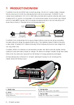
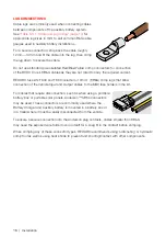
The BCDC Core Battery Chargers are equipped with a fly lead wiring harness that must be correctly
connected to ensure effective charging of the auxiliary battery. See
"Table 1.1.1: Wire Description"
for more information.
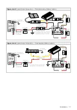
"3.2.1 Battery Setup" (page 12)
"3.7 Cable and Wire Installations" (page 19)
for
typical BCDC Core Battery Charger setups and wire installation details.
Table 1.1.1:
Wire Description
Wire Colour
Description
Length
Gauge
Purpose
Brown
Output Cable 392 mm / 15.4"
8 mm² / 8 AWG
Connects to the
auxiliary battery
Black
Ground Cable 424 mm / 16.7"
8 mm² / 8 AWG
Connects to the
common ground
Orange
Profile
Selection Wire
447 mm / 17.6" 0.5 mm² / 20 AWG
Used to configure the
Charge Profile.
Red
Vehicle Input
Cable
457 mm / 18"
8 mm² / 8 AWG
Connects to the vehicles
start battery positive terminal.
Blue
Vehicle Ignition
Wire
479 mm / 18.9" 0.5 mm² / 20 AWG
Connects to ignition
signal for vehicles with
Smart Alternators
Yellow
Solar Input
Cable
507 mm / 20"
8 mm² / 8 AWG
Connects to the solar
panel input positive
Green
External LED
Wire
484 mm / 19"
0.5 mm² / 20 AWG
Used to power optional LED /
connects to Orange Wire for
Lithium batteries.
1.2 Charge Profile LEDs
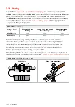
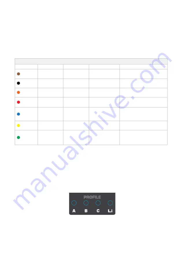
The Dual Input In-cabin BCDC Core features four different charging profiles designed to suit your
battery’s charging requirements. The BCDC Core supports AGM/Gel
(A),
Standard Lead Acid
(B)
,
Calcium
(C)
and Lithium
(Li)
profiled batteries. Refer to the charging specifications stated by the
battery manufacturer, and the installation temperature chart before selecting the profile for your
installation (see
"Table 3.7.3.1: Charge Profile Selection for Cabin Installation" (page 20)
).
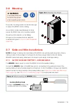
Profile LED
A.
AGM/Gel
C.
Calcium
B.
Lead Acid
Li.
Lithium
The selected Profile LED will be on solid when the unit is ON and charging. A flashing profile LED
indicates that the unit is in standby mode and ready to charge when the vehicle is turned on.
Summary of Contents for BCDCN1225
Page 34: ...34 NOTES ...
Page 35: ...35 ...


